Dummy load control circuit and flyback switching power supply circuit

A control circuit, dummy load technology, applied in the direction of high-efficiency power electronic conversion, electrical components, output power conversion devices, etc., can solve problems such as increased power consumption

Inactive Publication Date: 2015-12-16
万辽辽
View PDF0 Cites 4 Cited by
  • Summary
  • Abstract
  • Description
  • Claims
  • Application Information

AI Technical Summary

Problems solved by technology

[0003] However, in a traditional dual output flyback circuit, the main output (+12V) is closed-loop controlled with fully adjustable load accuracy, while the auxiliary output (+24V) is only semi-regulated (only controlled by the transformer winding)
When the main output is heavy-loaded and the auxiliary output is light-loaded, the voltage of the auxiliary output will fluctuate up to 35V. To stabilize the voltage accuracy of the auxiliary output, it is necessary to add a dummy load to the auxiliary output circuit, which will increase the power consumption during standby.

Method used


Image

  • Dummy load control circuit and flyback switching power supply circuit
  • Dummy load control circuit and flyback switching power supply circuit

Examples


Embodiment Construction

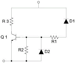
[0017] Please refer to figure 1 , is a schematic diagram of a dummy load control circuit in an embodiment.

[0018] The dummy load control circuit is used to be connected between the first output terminal and the second output terminal of the flyback switching power supply circuit with two outputs, including a first diode D1, a second diode D2, The first resistor R1, the second resistor R2, the dummy load device R3 and the first switch tube Q1.

[0019] The anode of the first diode D1 is connected to the control terminal of the first switching transistor Q1 through the first resistor R1, and the cathode of the first diode D1 is connected to the first output terminal. The anode of the second diode D2 is connected to the low potential end of the first switch tube Q1, the cathode of the second diode D2 is connected to the control terminal of the first switch tube Q1, and the second resistor R2 is connected in parallel to the second diode At both ends of D2, the high potential e...


PUM


Abstract

A dummy load control circuit is used between a first path output end and a second path output end of a flyback switching power supply circuit having two paths of outputs, and includes a first diode, a second diode, a first resistor, a second resistor, a dummy load device and a first switching tube; a positive electrode of the first diode is connected to a control end of the first switching tube through the first resistor, and a negative electrode of the first diode is connected to the first path output end; and a positive electrode of the second diode is connected with a low potential end of the first switching tube, a negative electrode of the second diode is connected with the control end of the first switching tube, the second resistor is connected to two ends of the second diode in parallel, and a high potential end of the first switching tube is connected to the first path output end through the dummy load device. Also disclosed is a flyback switching power supply circuit. The precision of auxiliary output voltage can be stabilized, and the standby power consumption is not affected.

Description

technical field [0001] The present application relates to the field of switching power supplies, in particular to a dummy load control circuit. Background technique [0002] The flyback conversion circuit is widely used in more than two output power supplies due to its simple topology, electrical isolation of input and output, wide range of step-up / down, and automatic load balancing of multiple output outputs. [0003] However, in a traditional dual output flyback circuit, the main output (+12V) is closed-loop controlled with fully adjustable load accuracy, while the auxiliary output (+24V) is only semi-regulated (only controlled by the transformer winding). When the main output is heavy-loaded and the auxiliary output is light-loaded, the voltage of the auxiliary output will fluctuate up to 35V. To stabilize the voltage accuracy of the auxiliary output, it is necessary to add a dummy load to the auxiliary output circuit, which will increase the power consumption during stan...

Claims


Application Information

Patent Timeline
Patent Type & Authority Applications(China)
IPC IPC(8): H02M1/00
CPCY02B70/10
Inventor 万辽辽
Owner 万辽辽
Why Eureka
Try Eureka