Flyback switching power supply

A switching power supply and flyback technology, applied in electrical components, adjusting electrical variables, instruments, etc., can solve problems such as damage to human body electric shock devices, and achieve the effect of avoiding device damage and human body electric shock

Active Publication Date: 2015-12-16
GUANGDONG OPPO MOBILE TELECOMM CORP LTD
View PDF6 Cites 3 Cited by
  • Summary
  • Abstract
  • Description
  • Claims
  • Application Information

AI Technical Summary

Problems solved by technology

[0006] The present invention provides a flyback switching power supply to solve the problems of human body electric shock and device damage t

Method used


Image

  • Flyback switching power supply
  • Flyback switching power supply
  • Flyback switching power supply

Examples


Embodiment 1

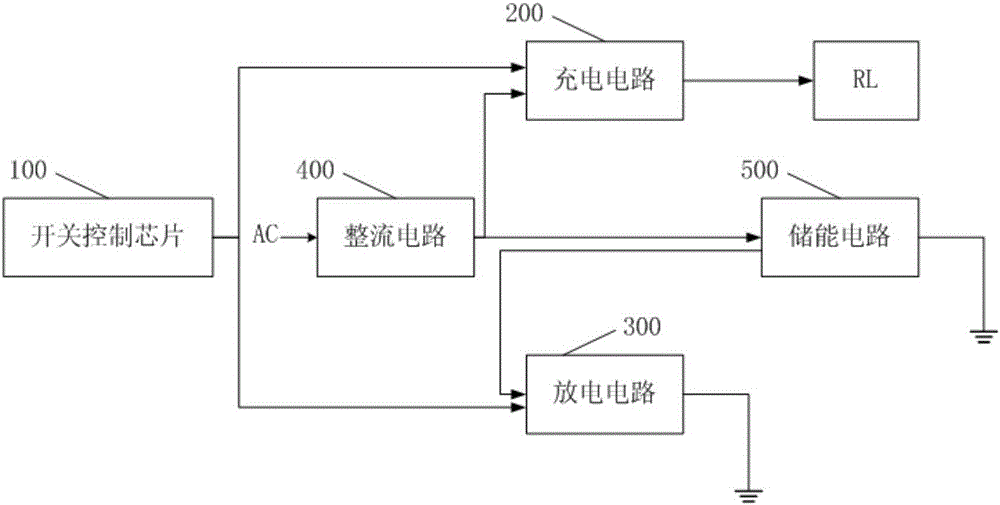
[0021] Such as figure 1 As shown, it is a structural diagram of a flyback switching power supply provided by Embodiment 1 of the present invention. The technical solution of this embodiment is suitable for processing the large amount of electricity stored in the energy storage circuit built in the flyback switching power supply after the input power is cut off. The flyback switching power supply is used to charge a load, and specifically includes: a switching control chip 100, a charging circuit 200, a discharging circuit 300, a rectifier circuit 400, and an energy storage circuit 500.

[0022] The output terminal of the switch control chip 100 is connected to the control terminal of the charging circuit 200, and the output terminal of the switch control chip 100 is also connected to the control terminal of the discharge circuit 300. The switch control chip 100 is used to output control signals to control the charging circuit 200 and the discharge circuit. 300. Specifically, the...

Embodiment 2

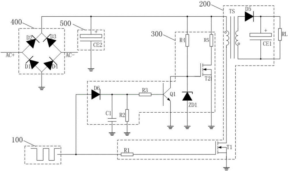
[0036] Such as figure 2 As shown, it is a circuit diagram of a flyback switching power supply provided in the second embodiment of the present invention. This embodiment is based on the first embodiment, after the input power is cut off, the large amount of electricity stored in the energy storage circuit 500 built in the flyback switching power supply is processed to solve the problems of the prior art.

[0037] The flyback switching power supply is used to charge the load RL, and specifically includes: a switch control chip 100, a charging circuit 200, a discharging circuit 300, a rectifier circuit 400, and an energy storage circuit 500.

[0038] When the flyback switching power supply is working, the AC signal terminal transmits an AC signal to the input terminal of the rectifier circuit 400, and the control signal output by the switch control chip 100 is a pulse signal, which controls the charging circuit 200 and the load RL to conduct and control simultaneously The discharge ...

Embodiment 3

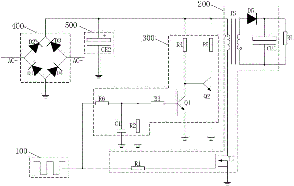
[0054] Such as image 3 As shown, it is a circuit diagram of a flyback switching power supply provided in the third embodiment of the present invention. This embodiment is based on the first embodiment. After the input power is cut off, the large amount of electricity stored in the energy storage circuit 500 built in the flyback switching power supply is processed to solve the problems of the prior art.

[0055] The flyback switching power supply is used to charge the load RL, and specifically includes: a switch control chip 100, a charging circuit 200, a discharging circuit 300, a rectifier circuit 400, and an energy storage circuit 500.

[0056] When the flyback switching power supply is working, the AC signal terminal transmits an AC signal to the input terminal of the rectifier circuit 400, and the control signal output by the switch control chip 100 is a pulse signal, which controls the charging circuit 200 and the load RL to conduct and control simultaneously The discharge ci...


PUM


Abstract

The invention discloses a flyback switching power supply used for charging a load. The power supply includes a switch control chip, a charge circuit, a discharge circuit, a rectification circuit and an energy storage circuit. The switch control chip outputs control signals and enables the charge circuit to connect with the load and enables the discharge circuit to disconnect with ground at the same time, or enables the charge circuit to disconnect with the load and enables the discharge circuit to connect with ground at the same time. The rectification circuit performs rectification on AC signals transmitted at the AC signal terminal so as to output DC signals. The charge circuit charges the load through the DC signals when being connected to the load. The energy storage circuit acquires the DC signals and stores energy or discharges through the discharge circuit. The discharge circuit disconnects with the ground or connects with the ground for discharge under the control of the control signals. According to the invention, the discharge circuit discharges to the energy storage circuit, so that electric shock and device damage caused by large electric quantity of the energy storage circuit when a prior flyback switching power supply stops working are avoided.

Description

Technical field [0001] The invention relates to a power supply discharge protection technology, in particular to a flyback switching power supply provided with a discharge circuit. Background technique [0002] Alternating current is alternating current, which is a current whose size and direction change periodically over time, while direct current is constant current, which is a current whose size and direction are constant. Alternating current is mostly used for power and energy supply, and is currently a general industrial and civilian feed power source, while direct current is mostly used for terminal electrical circuits. [0003] Since alternating current has no direction and reference value and cannot represent a logical state, most electronic devices use direct current. The power module of the electronic device receives AC power and performs power processing such as voltage transformation, rectification, and filtering on it, and then converts the AC power into the DC power ...

Claims


Application Information

Patent Timeline
IPC IPC(8): H02M1/32H02M3/335
Inventor 苏上丁
Owner GUANGDONG OPPO MOBILE TELECOMM CORP LTD
Why Eureka
Try Eureka