Oscillating head micromotor based on giant magnetostrictive material

A giant magnetostrictive and oscillating head technology, applied in the direction of piezoelectric effect/electrostrictive or magnetostrictive motors, generators/motors, electrical components, etc., can solve the problems of low efficiency and achieve large output displacement, Ease of Miniaturization, Fast Response Effects

Active Publication Date: 2018-01-19
SHANGHAI JIAOTONG UNIV
View PDF12 Cites 0 Cited by
  • Summary
  • Abstract
  • Description
  • Claims
  • Application Information

AI Technical Summary

Problems solved by technology

The magnetostrictive rods in the above drivers all work in a non-resonant state, so the efficiency is low

Method used


Image

  • Oscillating head micromotor based on giant magnetostrictive material
  • Oscillating head micromotor based on giant magnetostrictive material
  • Oscillating head micromotor based on giant magnetostrictive material

Examples


Embodiment 1

[0048] The oscillating head micromotor based on giant magnetostrictive materials includes a stator, a rotor and a pre-pressure system, specifically as Image 6 shown. The stator of the motor has a variety of structures, not limited to the structure in the figure. The magnetostrictive effect of the giant magnetostrictive material is mainly used to deform the giant magnetostrictive unit, thereby simultaneously exciting the two first-order bending vibration modes of the stator. state, so that the trajectory of the mass point on the driving end surface where the stator and the rotor are in contact is an ellipse, and the stator drives the rotor to rotate through friction.

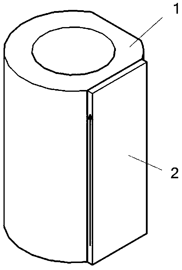
[0049] figure 1 It is a kind of construction method of the stator, which is composed of a magnetically deformable body (giant magnetostrictive material) 2 and a metal base 1 (metal material). Among them, the magnetic deformation body 2 is magnetized along the axial direction. Under the action of an external ma...

Embodiment 2

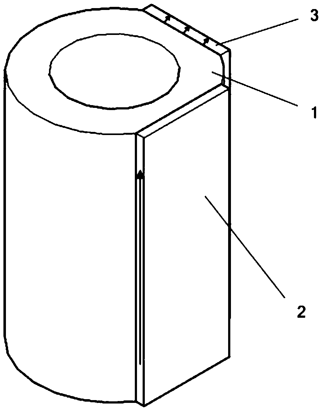
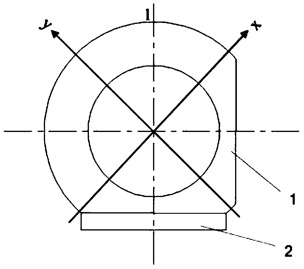
[0058] The micromotor includes a stator, a rotor and a pre-pressure system, specifically as Image 6 As shown, the stator structure is as figure 2 shown. figure 2 Among them, 3 is the piezoelectric material body (piezoelectric material), the direction of the arrow is the polarization direction of the piezoelectric material body, 1 is the metal matrix (metal material), 2 is the magnetically deformable body (giant magnetostrictive material), the direction of the arrow is is the magnetization direction of the magnetically deformable body. Under the action of an external magnetic field, due to the magnetostrictive effect of the giant magnetostrictive material, the stator deforms along the direction 1 ( image 3 shown), so that two first-order bending vibration modes of the stator along the x and y directions can be simultaneously excited. The superposition of the two vibrations forms the bending vibration of the stator cylinder, so that the movement track of the mass point on...


PUM


Abstract

The invention provides a giant magnetostrictive material-based rocking head type micromotor, which comprises a stator, a rotor and a precompression system, wherein the stator comprises a magnetic deformation body and a metal base body; a magnetostrictor body extends along the magnetization direction under the action of the applied magnetic field; two first-order bending vibration modes with a certain included angle in space are excited on the stator; the motion track of a mass point on a contact drive end surface of the stator and the rotor is an ellipse; the rotor runs through the hollow stator and is pressed on a drive end of the stator under the action of the precompression system; and the stator drives the rotor to rotate through friction. According to the giant magnetostrictive material-based rocking head type micromotor, wireless driving is achieved by external magnetic field excitation; microminiaturization is easy to achieve; and a piezoelectric material body is used for monitoring the running state of the motor in real time, and can also be used as a magnetoelectric conversion unit for achieving wireless energy supply and the like. The giant magnetostrictive material-based rocking head type micromotor is especially suitable for the occasions, such as the fields of medical diagnosis, robots and the like, which require accurate positioning.

Description

technical field [0001] The invention relates to a device in the application field of giant magnetostrictive materials, in particular to a shaking head external magnetically controlled micromotor based on giant magnetostrictive materials suitable for wireless driving. Background technique [0002] The oscillating head motor is an important type of piezoelectric motor. Generally, the oscillating head motor utilizes two symmetrical first-order bending vibration modes of the stator. The combination of these two vibrations makes the particle on the end face of the stator drive generate an elliptical motion trajectory, and then The rotor is driven to rotate by the friction between the stator and the rotor. Oscillating piezoelectric motors based on bending vibration modes have been a research hotspot in the field of micro-actuators in recent years due to their simple structure, convenient processing, low cost, light weight and small size. At present, some moving head micro-motors ...

Claims


Application Information

Patent Timeline
Patent Type & Authority Patents(China)
IPC IPC(8): H02N2/00H02N2/02
CPCH02N2/003H02N2/0065H02N2/007H02N2/026
Inventor 鹿存跃李冲马艺馨
Owner SHANGHAI JIAOTONG UNIV
Why Eureka
Try Eureka