Supercharge Your Innovation With Domain-Expert AI Agents!

Crankshaft for reciprocating piston engine

一种活塞式发动机、曲轴的技术,应用在曲轴等方向,能够解决困难等问题

Active Publication Date: 2015-12-16
MERCEDES BENZ GRP
View PDF6 Cites 0 Cited by
  • Summary
  • Abstract
  • Description
  • Claims
  • Application Information

AI Technical Summary

Problems solved by technology

However, this machining step is subject to particularly difficult process guidance, since particularly long drilling tools are required for drilling through the crankshaft within the scope of a single machining step, which are particularly centered and correspondingly aligned with each other. Particularly small axial dislocations create corresponding holes

Method used


Image

  • Crankshaft for reciprocating piston engine
  • Crankshaft for reciprocating piston engine
  • Crankshaft for reciprocating piston engine

Examples


Embodiment Construction

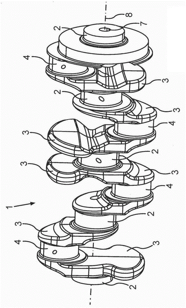
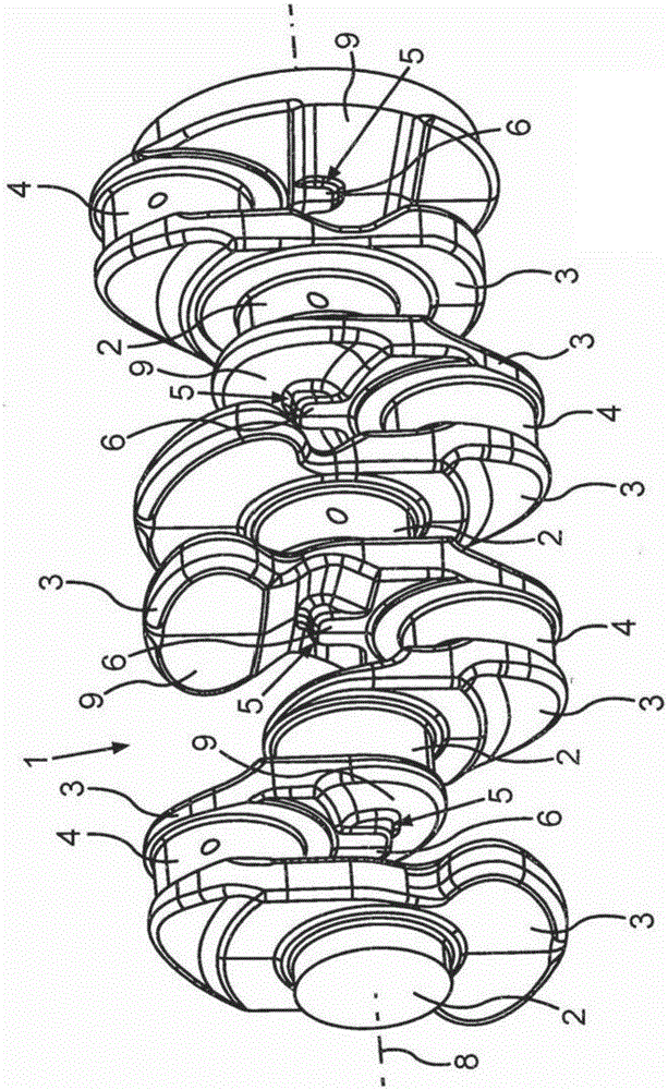
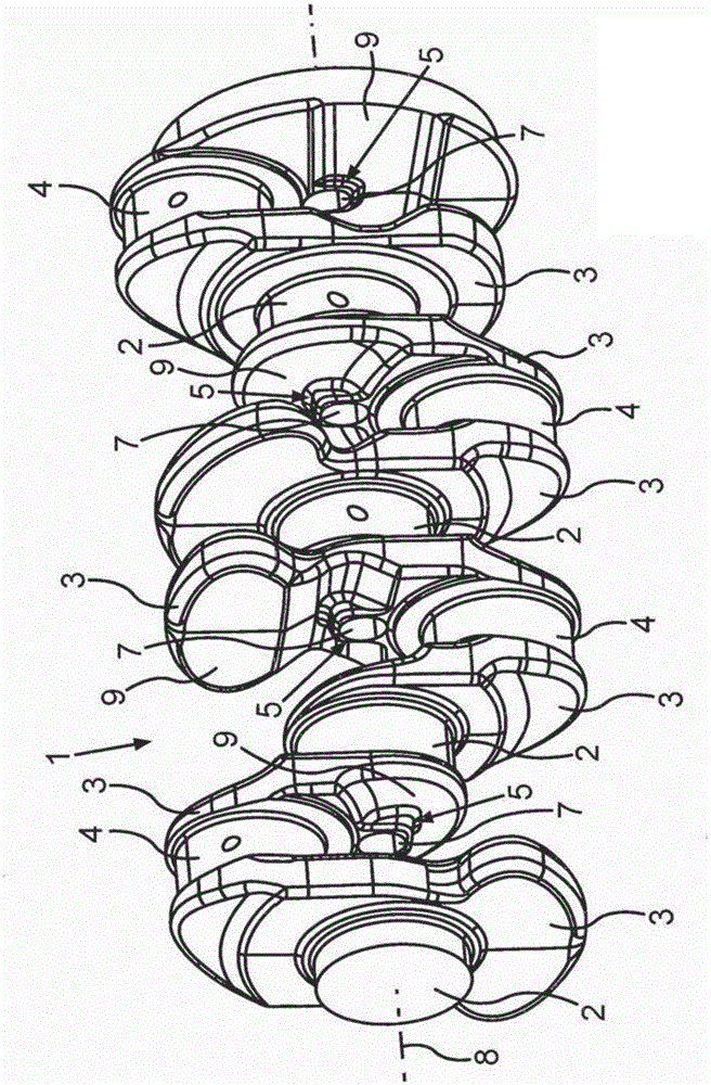
[0016] The crankshaft 1 known from the prior art is shown in a schematic perspective view figure 1 Shown in. It is known that the crankshaft 1 is supported in a crankshaft bearing (not shown here) of a piston engine by means of a corresponding journal 2. The crankshaft 1 basically rotates around a rotation axis 8, which at the same time corresponds to the center line of the through hole 7 of the crankshaft 1. During the rotation of the journal 2 only in its corresponding bearing about the axis of rotation 8 and therefore about its corresponding longitudinal axis, the corresponding connecting rod journal 4 (the connecting rod journal is connected by means of the corresponding crank arm 3 to the journal 2 Connection) basically depicts a circular orbit around the axis of rotation 8. The connecting rod journals 4 are surrounded by corresponding connecting rod bearings of connecting rods not shown here, wherein the number of connecting rod journals 4 is equal to the number of cylin...


PUM


Abstract

The invention relates to a crankshaft (1) for a reciprocating piston engine, comprising at least one journal (2) joined to crank webs (3) that are connected to each other by a crank pins (4). On the crank webs (3) and near an axis of rotation (8), material accumulations (5) are provided, each having a surface (6) which is at least substantially perpendicular to the axis of rotation (8).

Description

Technical field [0001] The invention relates to a crankshaft for a piston engine according to the preamble of claim 1. Background technique [0002] It is known from the prior art that the crankshaft of a piston engine is subject to high torques and particularly high load changes and therefore must have a particularly high load change intensity. A common manufacturing method of a crankshaft includes not only a forging process but also a casting process, in which the rough state of the corresponding crankshaft is first produced, and then the crankshaft is subjected to corresponding final processing steps according to corresponding requirements. The final processing steps include, for example, crankshaft balancing (Wuchten) in order to eliminate uneven rotation of the crankshaft, or surface processing of the corresponding journals, which correspond to the corresponding bearings of the engine or the corresponding connecting rod bearings. . In addition to the surface processing of ...

Claims


Application Information

Patent Timeline
Patent Type & Authority Applications(China)
IPC IPC(8): F16C3/08
CPCF16C3/08F16C3/06
Inventor H·布罗伊宁C·哈姆斯F·利布曼U·维登曼U·霍尔特曼
Owner MERCEDES BENZ GRP
Features
  • R&D
  • Intellectual Property
  • Life Sciences
  • Materials
  • Tech Scout
  • Unparalleled Data Quality
  • Higher Quality Content
  • 60% Fewer Hallucinations
Learn More