Sand mold recovery equipment

A technology for recycling equipment and sand molds, which is applied to casting molding equipment, metal processing equipment, and machinery for cleaning/processing mold materials, etc. It can solve the problems of large energy consumption by fans, reduced efficiency of iron filings removal, and dust. , to achieve the effect of improving the degree of cleaning, saving management time, and facilitating recycling

Inactive Publication Date: 2015-12-23
NINGGUO SOUTHERN WEAR RESISTANT MATERIALS
View PDF4 Cites 11 Cited by
  • Summary
  • Abstract
  • Description
  • Claims
  • Application Information

AI Technical Summary

Problems solved by technology

At present, when the traditional mold box is used to produce casting products, there are often iron impurities adsorbed on the surface of the molding sand that are difficult to remove, and even small metal pieces. In order to often remove the iron impurities adsorbed on the surface of the old molding sand, and there is dust in the molding sand , which is difficult to remove and affects the quality of casting products; in order to improve the quality of casting products, recycling old sand is a necessary procedure in industrial production, which can also reduce production costs
[0003] The Chinese patent announcement number is CN203556788U. The patent uses the blower to suck up the molding sand through the air inlet pipe, and then separates the dust from the molding sand through the dust outlet pipe, and separates the molding sand and iron filings through the magnet in the storage tower. Separation of iron filings and dust, but in the process of use, the molding sand is sucked into the air inlet pipe, which requires a lot of energy consumed by the fan, and a large amount of molding sand will accumulate in the sand pit, the filter is easy to block, and in the storage tower, the iron filings are easy to mix with the molding sand They fall into the bottom of the storage together, resulting in low removal efficiency of iron filings, and the iron filings on the surface of the magnet are not easy to clean. After long-term use, the removal efficiency of iron filings in the molding sand is further reduced.

Method used


Image

  • Sand mold recovery equipment

Examples


Embodiment Construction

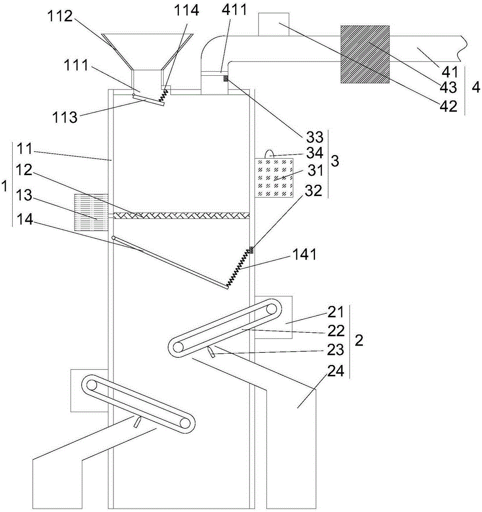
[0019] refer to figure 1 As shown, a kind of sand recovery equipment proposed by the present invention includes a raw sand recovery mechanism 1, a plurality of iron scrap recovery mechanisms 2 and a comprehensive control mechanism 3;

[0020] Raw sand recovery mechanism 1 includes raw sand recovery box 11, filter screen 12, vibrating motor 13 and sand guide plate 14; raw sand recovery box 11 is provided with sand inlet 111, filter screen 12 is installed in the raw sand recovery box 11 and is located The lower end of the sand inlet 111, the vibrating motor 13 is connected with the filter screen, the sand guide plate 14 is installed obliquely in the raw sand recovery box 11, and the end of the sand guide plate 14 located in the inclined direction is movably connected with the inner wall of the raw sand recovery box 11, and the sand guide plate 14 The end away from the inclined direction is connected to the inner wall of the raw sand recovery box 11 by the first spring 141;

[0...


PUM


Abstract

The invention proposes sand mold recovery equipment. The sand mold recovery equipment comprises a crude sand recovery mechanism, multiple iron chip recovery mechanisms and a comprehensive control mechanism, wherein the crude sand recovery mechanism comprises a crude sand recovery box, a filter screen, a vibration motor and a sand guide plate; a sand inlet sand guide plate is aslant mounted in the crude sand recovery box; one end, in the inclined direction, of the sand guide plate is movably connected with the inner wall of the crude sand recovery box; one end, far from the inclined direction, of the sand guide plate is connected with the inner wall of the crude sand recovery box through a first spring; the iron chip recovery mechanisms comprise driving devices, magnetic conveying belts, chip scraping plates and chip guide pipes; the comprehensive control mechanism comprises a control device and a tensile sensor; the control device is in communication connection with the tensile sensor, the vibration motor and the driving device; and the control device obtains tensile signals of the tensile sensor, and controls the vibration motor and the driving device to work. The sand mold recovery equipment can effectively remove iron chips and dust in sand molds.

Description

technical field [0001] The invention relates to equipment for recycling molding sand, in particular to equipment for recycling sand molds. Background technique [0002] Molding sand is a material used for modeling in casting. Molding sand is generally made by mixing molding materials such as raw sand for casting, molding sand binder and auxiliary additives in a certain proportion. Molding sand can be divided into clay sand, water glass sand, cement sand, resin sand, etc. according to the different binders used. Clay sand, water glass sand and resin sand are the most used. At present, when the traditional mold box is used to produce casting products, there are often iron impurities adsorbed on the surface of the molding sand that are difficult to remove, and even small metal pieces. In order to often remove the iron impurities adsorbed on the surface of the old molding sand, and there is dust in the molding sand , It is difficult to remove, which affects the quality of cas...

Claims


Application Information

Patent Timeline
Patent Type & Authority Applications(China)
IPC IPC(8): B22C5/06B22C5/00
Inventor 熊夏鸣
Owner NINGGUO SOUTHERN WEAR RESISTANT MATERIALS
Why Eureka
Try Eureka