Three-jaw self-centering chuck clamping device

A self-centering chuck and clamping device technology, applied in auxiliary devices, auxiliary welding equipment, welding/cutting auxiliary equipment, etc., can solve the problems of poor workpiece quality, low processing efficiency, and high cost

Active Publication Date: 2015-12-23
HIMILE MECHANICAL MFG
View PDF9 Cites 5 Cited by
  • Summary
  • Abstract
  • Description
  • Claims
  • Application Information

AI Technical Summary

Problems solved by technology

Since there are many types and specifications of workpieces to be processed, and the sizes are different, it brings a lot of inconvenience to the processing.
Generally speaking, simple tooling such as roller frames is used to fix, and manual cutting, drilling, welding, etc. ar...

Method used


Image

  • Three-jaw self-centering chuck clamping device
  • Three-jaw self-centering chuck clamping device
  • Three-jaw self-centering chuck clamping device

Examples


Embodiment Construction

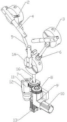
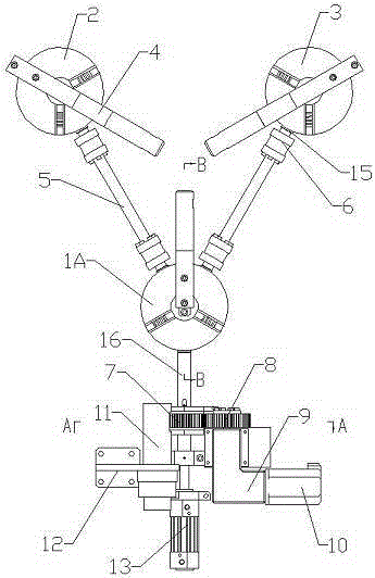
[0029] Examples such as figure 1 , figure 2 As shown, a three-jaw self-centering chuck clamping device is composed of three centering chucks arranged in a triangle, and the three centering chucks are driven by the same power and synchronously linked to realize self-centering Function.

[0030] The three centering chucks include a main chuck 1A, a sub-chuck 2 and a sub-chuck 3 that are uniformly distributed at 120 degrees on the same plane; each chuck is provided with a clamping rod 4 .

[0031] The clamping rod 4 and the claw 17 are connected by threads, and changing the clamping rod 4 of different lengths can realize the clamping of a wide range of pipe fittings with different diameters.

[0032] The main chuck 1A is connected with the auxiliary chuck 2 and the auxiliary chuck 3 respectively through connecting rods 5; both ends of the connecting rod 5 are respectively connected with connecting heads 15 through rigid couplings 6;

[0033] The connectors 15 close to the sub...


PUM


Abstract

The invention discloses a three-jaw self-centering chuck clamping device. The three-jaw self-centering chuck clamping device is composed of three centering chucks distributed in a triangular shape, and the three centering chucks are driven by the same power and linked synchronously, so that a self-centering function is achieved. According to the three-jaw self-centering chuck clamping device, the centering chucks are adopted, so that the device is especially suitable for automatic backing welding of a connecting pipe with flanges on the two sides and the flanges, and the workpiece can be directly lifted away along the chucks after being welded.

Description

technical field [0001] The invention relates to a tooling tool for automatic welding of circular workpieces and flame drilling and blanking, especially a three-jaw automatic welding tool used for automatic welding of some long pipe fittings and workpieces with flanges at both ends. A clamping device for a centering chuck belongs to the technical field of mechanical processing tooling. Background technique [0002] In petroleum, natural gas, chemical and other industries, it is necessary to process round workpieces, such as pipe cutting, drilling, welding, etc. Since there are many types and specifications of the workpieces to be processed, and the sizes are different, it brings a lot of inconvenience to the processing. Generally speaking, simple tooling such as roller frames is used to fix, and manual cutting, drilling, welding, etc. are performed. Due to uneven application of force, this fixing method may accidentally fall off during processing, and the center accuracy of ...

Claims


Application Information

Patent Timeline
IPC IPC(8): B23K37/053
CPCB23K37/0536
Inventor 姜雄德秦启伟迟丰涛魏效辉魏猛张增军
Owner HIMILE MECHANICAL MFG
Why Eureka
Try Eureka