Arc type clamping device

A clamping device and arc technology, applied in the direction of clamping device, positioning device, clamping, etc., can solve the problems of complex working principle and complex overall structure, and achieve the effect of simple working principle and simple overall structure.

Inactive Publication Date: 2015-12-23
CHONGQING YOUBO MACHINERY MFG
1 Cites 4 Cited by

AI-Extracted Technical Summary

Problems solved by technology

[0005] This bowl-shaped workpiece clamping device with a hole in the bottom is mainly fixed by the relative movement between the piston rod 1, the driving column wedge 2, the two plungers 4, the return spring 6, a...

Method used

The upper end of stud bolt 3 is fixedly realized by the connection between nut 4, positioning block 4 and upper base 111, and the lower end of stud bolt 3 is fixedly realized by the connection of nut 4 and lower base 112, screw Move the upper nut 4 to press down the positioning block 2, so that the positioning block 2 and the clamping part ...

Abstract

The invention relates to the field of clamping devices, in particular to an arc type clamping device. The arc type clamping device comprises a base, a positioning block, a stud, nuts and a clamping portion. The base comprises an upper base body and a lower base body. The positioning block is clamped to the upper surface of the upper base body. A workpiece is placed on the upper surface of the lower base body. The stud penetrates the positioning block to reach the lower base body and is arranged in the lower base body. The upper end of the stud is fixed to the upper surface of the positioning block through one nut. The lower end of the stud is fixed to the upper surface of the lower base body through another nut. The clamping portion is arranged on the lower surface of the upper base body and clamps the lower end of the positioning block and the stud. The other end of the clamping portion abuts against the workpiece. The clamping portion is matched with the lower surface of the upper base body, the lower end of the positioning block and the contact face of the stud. The arc type clamping device is simple in structure and simple in working principle.

Application Domain

Technology Topic

Image

  • Arc type clamping device
  • Arc type clamping device

Examples

  • Experimental program(1)

Example Embodiment

[0015] Example one
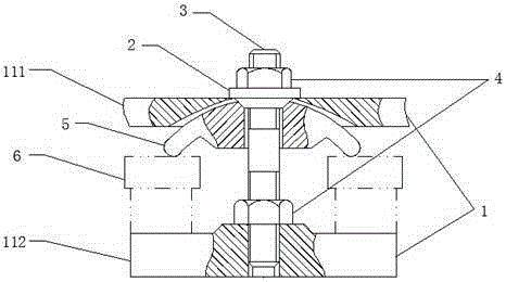
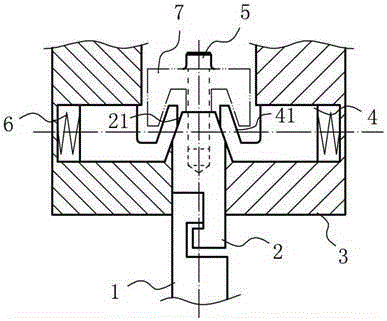
[0016] An arc type clamping device includes a base 1, a positioning block 2, a stud bolt 3, a nut 4 and a clamping part 5. The base 1 includes an upper base 111 and a lower base 112. The positioning block 2 is clamped on the upper surface of the upper base 111, the stud bolt 3 penetrates the positioning block 2 to the lower base 112 and is arranged inside the lower base 112, and the upper end of the stud bolt 3 is fixed by a nut 4 On the upper surface of the positioning block 2, the lower end of the stud bolt 3 is fixed to the upper surface of the lower base 112 by the nut 4, and the clamping portion 5 is provided on the lower surface of the upper base 111 and clamps the lower end of the positioning block 2 and For the stud bolt 3, the lower surface of the upper base 111 is set in an arc shape, the contact surface of the clamping portion 5 and the lower surface of the upper base 111 is set in a matching arc shape, and the clamping The end of the part 5 in contact with the workpiece 6 is set in an arc shape.
[0017] The upper end of the stud bolt 3 is fixed by the connection between the nut 4, the positioning block 4 and the upper base 111, and the lower end of the stud bolt 3 is fixed by the connection between the nut 4 and the lower base 112. The nut 4 presses down the positioning block 2 to make the positioning block 2 abut the clamping part 5 to realize the clamping of the workpiece 6. The contact surface of the clamping part 5 and the lower surface of the upper base 111 is set in a matching arc The shape is to push the positioning block 2 when the nut 4 on the upper base 111 is screwed down to make the clamping part 5 more evenly stressed.

PUM

no PUM

Description & Claims & Application Information

We can also present the details of the Description, Claims and Application information to help users get a comprehensive understanding of the technical details of the patent, such as background art, summary of invention, brief description of drawings, description of embodiments, and other original content. On the other hand, users can also determine the specific scope of protection of the technology through the list of claims; as well as understand the changes in the life cycle of the technology with the presentation of the patent timeline. Login to view more.

Similar technology patents

Integrated embedded pipe hot stamping die for automobile parts

InactiveCN102029310AManufacturing process cycle and cost reductionThe overall structure is simpleShaping toolsMotor vehicle partHot stamping
Owner:BAOSHAN IRON & STEEL CO LTD

Classification and recommendation of technical efficacy words

  • The overall structure is simple
  • Simple working principle

Time frequency analysis based loudspeaker noise online detecting instrument

InactiveCN101115329AThe overall structure is simpleLow installation and manufacturing costsElectrical apparatusTime–frequency analysisLoudspeaker
Owner:TIANJIN UNIVERSITY OF SCIENCE AND TECHNOLOGY +1

Safety rod driving system of liquid heavy metal cooling reactor

Owner:HEFEI INSTITUTES OF PHYSICAL SCIENCE - CHINESE ACAD OF SCI
Why Eureka
Try Eureka