

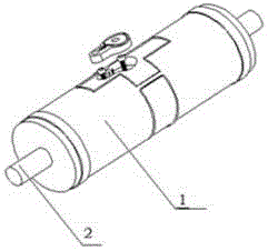
Waste discharging device for knife roll of rotary die-cutting machine
A technology of a waste discharge device and a die-cutting machine, which is applied in metal processing, etc., can solve problems such as incomplete waste discharge, reduced work efficiency, and knife edge extrusion and chipping, and achieves the effects of reduced production costs, simple structure, and convenient use
- Summary
- Abstract
- Description
- Claims
- Application Information
AI Technical Summary
Problems solved by technology
Method used
Image

Examples
Embodiment Construction
[0016] In order to make the technical means, creative features, goals and effects achieved by the present invention easy to understand, the present invention will be further described below in conjunction with specific embodiments.
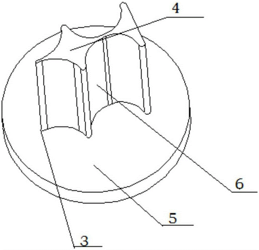
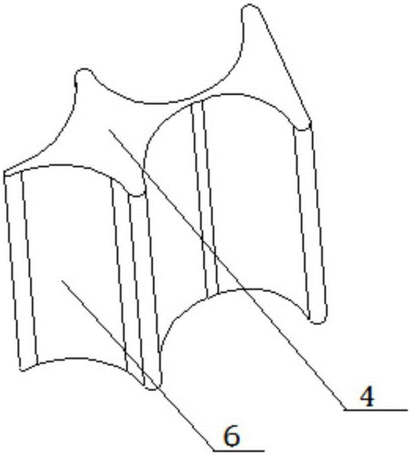
[0017] In view of the diversification of market products, ordinary switchblades can no longer meet the requirements. As the gap between products is getting smaller and smaller, the graphics are becoming more and more irregular. Common thimbles require a gap of more than 0.8mm, while products with a gap between 0.2-0.8mm More and more, because ordinary thimbles are a whole, it is not practical for products with various shapes and small gaps, and the waste discharge is not complete, which indirectly affects the service life of the knife roller and reduces work efficiency. The waste discharge requirement is imminent. The common thimble is a whole, and the special-shaped thimble of the present invention is divided into two parts, one part is the needle...
PUM
 Abstract
Description
Claims
Application Information