
a hole reaming machine

A technology of a hole reaming machine and a rack, which is applied in the field of reaming machines, can solve the problems of low production efficiency of production lines, damage to metal pipes, and high temperature, and achieve the effect of improving production efficiency.

Active Publication Date: 2016-06-01
高密天一机械科技有限公司
View PDF6 Cites 0 Cited by
  • Summary
  • Abstract
  • Description
  • Claims
  • Application Information

AI Technical Summary

Problems solved by technology

Both ends of the metal tube are manually punched with process holes. The punching accuracy is low and unreliable. It is difficult to ensure that the process holes at both ends of the metal tube are located at the same center line along the metal tube axis on the outer peripheral surface of the metal tube. On a straight line, when the metal pipe is hoisted by hooking the process hole in the subsequent sequence, the metal pipe is prone to twisting and skewing, and what is more serious, the metal pipe may even be decoupled, causing accidents
[0006] 2. The production line is used. The production line is long and occupies a large area, and only one metal tube can be processed at a time. One metal tube can only be processed after heating and reaming at the end. The production line is longer , the long conveying time and the inability of each station to process at the same time make the entire production line inefficient
[0007] 3. The length of the production line is long, and the sprocket chain is used to drive the metal pipes one by one on the conveying track, which consumes a lot of power. The conveying efficiency is low due to the one-by-one transportation and the long length of the production line, which makes the production efficiency of the entire production line low.
And the chain is easy to loose, so that the feeding of the metal tube is not accurate, and the metal tube cannot be accurately reached to the position to be heated or to be reamed, which affects the production efficiency
[0008] 4. The heating device on the existing production line adopts an electromagnetic heating device. Due to the high power, the temperature of the electromagnetic heating coil of the electromagnetic heating device is relatively high, which makes the outer insulating layer of the coil easy to heat up and scorched, and even cause a fire
The electromagnetic heating coil of the electromagnetic heating device on the existing production line is generally exposed to the outside. The exposed electromagnetic heating coil is easy to fall on the iron slag and cause the coil to short circuit.
[0009] 5. The front and rear diameters of the reaming head on the existing production line are the same, and only the front end is provided with a tapered chamfer. During the use of this reaming head, if the end of the metal pipe to be reamed is deformed, Bending causes part of the pipe wall of the metal pipe to deviate from the center, and the reaming head of the existing structure cannot automatically adjust the deviation of the metal pipe, which will cause the reaming of the end of the metal pipe to appear such as skew, uneven pipe wall, If it is off-center, it will even cause cracks at the reaming part of the end of the metal pipe, which will damage the metal pipe
In addition, the conical chamfer at the front end of the existing reaming head concentrates the stress at the beginning and end of the reaming transition of the metal pipe, which easily causes cracks in the metal pipe
Therefore, the existing reaming head makes the metal pipe reaming waste rate high
[0010] 6. In the existing metal pipe reaming production line, the jaw cylinder corresponding to the reaming head is set above the conveying track, so that the overall height of the production line equipment is high, and the piston rod of the cylinder drives the jaw down to move the end of the metal pipe. It is easy to shake when the part is positioned, and cannot withstand the force of the metal pipe when the hole is expanded.
When using the reaming head to ream the end of the metal pipe, the shaking jaws cannot hold the metal pipe, and the metal pipe shakes together, which affects the quality of the reaming at the end of the metal pipe
[0011] 7. In the existing metal tube reaming production line, the electromagnetic heating coil of the electromagnetic heating device is fixed on the conveying track, and the end of the metal tube needs to be pushed into the inside of the electromagnetic heating coil for heating, which is time-consuming and laborious

Method used


Image

  • a hole reaming machine
  • a hole reaming machine
  • a hole reaming machine

Examples


Embodiment 1

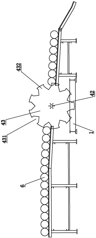
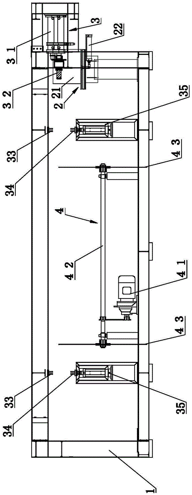
[0054] figure 1 It is a structural schematic diagram of Embodiment 1 of the hole reaming machine of the present invention; figure 2 It is another structural schematic diagram of Embodiment 1 of the hole reaming machine of the present invention.

[0055] refer to figure 1 and figure 2 , a hole reaming machine, comprising a frame 1, on which an electromagnetic heating device 2 and a hole reaming device 3 are sequentially arranged from front to back; the electromagnetic heating device 2 includes an electromagnetic heating coil 21, and the hole reaming device 3 includes a first power unit 31 drives the reaming head 32. In the present embodiment, the first power unit 31 adopts a hydraulic cylinder. Rotating shaft 42, rotating shaft 42 is arranged on the frame 1 through the lateral rotation of the bearing, the second power device 41 adopts a motor, and the motor and the rotating shaft 42 are connected by a sprocket chain transmission, and the two ends of the rotating shaft 42 a...

Embodiment 2

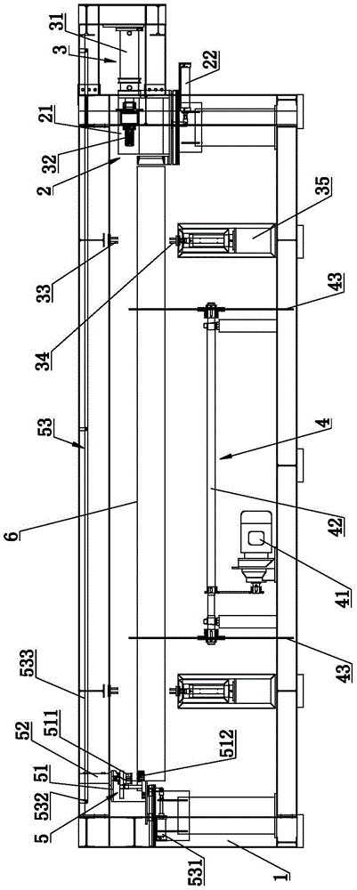
[0061] image 3 It is a structural schematic diagram of the second embodiment of the hole reaming machine of the present invention; Figure 4 It is a top view structure schematic diagram of the second embodiment of the hole reaming machine of the present invention; Figure 5 It is a structural schematic diagram of the process hole punching linkage device in the second embodiment of the hole reaming machine of the present invention; Figure 6 yes Figure 5 Schematic diagram of the punch holder in .

[0062] refer to image 3 , Figure 4 , Figure 5 as well as Figure 6 , the structure of this embodiment is basically the same as that of Embodiment 1, and the difference is that: for the reaming machine of this embodiment, the two ends of the frame 1 are respectively provided with a process hole punching device 5, and the process hole punching device 5 includes punching The head frame 51, the top of the punch frame 51 is fixedly provided with a punch 511 driven by the fourt...

Embodiment 3

[0069] Figure 7 It is a structural schematic diagram of the punch in the third embodiment of the hole reaming machine of the present invention; Figure 8 yes Figure 7 A schematic diagram of the three-dimensional structure.

[0070] refer to Figure 7 and Figure 8 , the structure of this embodiment is basically the same as that of Embodiment 2, the difference is that the punch 511 includes a punch body 5111, the periphery of the punch body 5111 is covered with an elastic rod 5112, and the elastic rod 5112 is provided with a punch body 5111 The diameter of the through hole on the elastic rod 5112 is smaller than the diameter of the punch body 5111 ; the head of the punch body 5111 retracts into the elastic rod 5112 .

[0071] In this embodiment, the elastic rod 5112 is a polyester rod, and the lower end of the polyester rod is covered with a metal sheath 5113. The metal sheath 5113 includes a bottom guard plate, and a ring guard plate is vertically connected to the periph...


PUM


Abstract

The invention discloses a reamer. The reamer comprises a rack, wherein the rack is provided with an electromagnetic heating device and a reaming device which are arranged from front to back in sequence; the electromagnetic heating device comprises an electromagnetic heating coil; the reaming device comprises a reaming hole driven by a first power device; the rack is provided with a poking plate feeding device; the poking plate feeding device comprises a rotating shaft connected with a second power device; the rotating shaft is transversely arranged on the rack; the two ends of the rotating shaft are fixedly provided with circular poking plates; the peripheral parts of the poking plates are provided with at least three feeding fork entries for conveying metal pipes; poking plates are formed between adjacent feeding fork entries and can rotate to the positions, corresponding to the electromagnetic heating coil and a reaming head, on every two adjacent feeding fork entries respectively. The reamer has the advantages of high production efficiency, small floor area and low power consumption.

Description

technical field [0001] The invention relates to the technical field of equipment for reaming the inner diameter of the end of a metal pipe, in particular to a reaming machine. Background technique [0002] In some engineering fields, it is necessary to splice multiple sections of metal pipes to form a conveying pipe or casing. At the splicing of the pipes, it is generally necessary to expand the inner diameter of one end of a section of the pipe to increase the inner diameter of the end of the pipe. Thereby, another section of pipeline to be spliced ​​can be inserted into the reaming end of this section of pipeline, so as to perform splicing better. For example, for steel pipe casings for covering cables, optical cables, and communication lines, etc., the ends of the steel pipe casings need to be reamed in inner diameter to splice multiple sections of steel pipe casings. In actual production, steel pipes used in this engineering field generally need to heat the end of the m...

Claims


Application Information

Patent Timeline
Patent Type & Authority Patents(China)
IPC IPC(8): B21D41/02
CPCB21D37/16B21D41/02B21D43/006B21D43/027B21D43/14
Inventor 罗峰邓志昌栾秀丽罗旭成
Owner 高密天一机械科技有限公司
Learn More