Electric driving wheel system

An electric drive and power technology, applied in the direction of electric components, electrical components, electromechanical devices, etc., can solve the problems of low torque density, high heat production, poor economy, etc., to reduce frictional heat, increase transfer efficiency, increase economical effect

Active Publication Date: 2015-12-23
BEIJING INST OF SPACE LAUNCH TECH +2
View PDF8 Cites 9 Cited by
  • Summary
  • Abstract
  • Description
  • Claims
  • Application Information

AI Technical Summary

Problems solved by technology

[0008] The purpose of the present invention is to provide an electric drive wheel system to solve the problems of low torque density, high heat production, poor economy and low reliability in the traditional electric drive wheel structure

Method used


Image

  • Electric driving wheel system
  • Electric driving wheel system
  • Electric driving wheel system

Examples


Embodiment 1

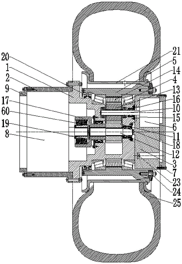
[0032] In the electric drive wheel system in this embodiment, at least one planetary gear power input motor provides multi-power source power for the auxiliary motor through at least one planetary gear power input motor, wherein the power transmitted by the auxiliary motor needs to be adjusted by the power The components are adjusted to match the power of the main motor and transmitted to the power coupled transmission components. The power coupling transmission assembly adopts a single-stage planetary gear row for power transmission, proportional conversion and coupling output. That is to say, multiple planetary gear power input motors are used as the main motor unit, and the power output is directly transmitted to the planetary gears, and then output to the hub after deceleration and torque increase of the planetary gears and ring gears; the sun gear power input motors are used as auxiliary motors It is a large-power motor, and its power output is adjusted by the power adjus...

Embodiment 2

[0068] In this implementation, a harmonic gear is used to replace the power coupling assembly in Embodiment 1, that is, the structure of the planetary gear. The harmonic gear mainly includes a power generator, a flex spline and a steel wheel. When using the harmonic gear to replace the structure in Example 1, there is only one main motor in the structure, which is directly connected to the steel wheel. The auxiliary motor is connected to the steel wheel through a magneto-rheological clutch. The power generator is connected. The power of the main motor is directly transmitted, and the power of the auxiliary motor is output after the adjustment of the clutch and the deceleration and torque increase of the flex spline and steel wheel. Under the condition of low torque demand, the main motor works alone. Under the condition of high torque demand, the main and auxiliary motors work together to provide coupling power, and the power coupling is completed at the joint of the flex spli...

Embodiment 3

[0070] In this embodiment, active gears are used to replace the power coupling assembly in Embodiment 1, that is, the planetary gear structure. The active gear mainly includes a shock wave device, a live gear, and a center wheel, which are similar to the harmonic gear. When replacing the inventive mechanism in Embodiment 1, there is one main motor, which is directly connected to the center wheel, and the auxiliary motor passes through the magneto-rheological The clutch is connected to the shock. The main motor directly drives the center wheel to rotate for power transmission; the auxiliary motor drives the shock wave to rotate through the adjustment of the clutch, and the power output is performed after the live gear and the center wheel decelerate and increase torque. Under the condition of low torque demand, the main motor works alone. Under the condition of high torque demand, the main motor and auxiliary motor work together to provide coupling power. The power coupling is ...


PUM


Abstract

The invention discloses an electric driving wheel system which comprises a source power assembly, a power adjusting assembly and a power coupling transmission assembly. The source power assembly comprises a main motor set and an auxiliary motor. The auxiliary motor is connected with the power adjusting assembly. The power adjusting assembly is connected with the power coupling assembly. The main motor set is connected with the power coupling assembly. The source power assembly is used for producing and transferring power. The power adjusting assembly is used for adjusting the power transferred by the auxiliary motor to be matched with the power of the main motor through the conversion between the solid state and the liquid state of magnetorheological fluid and transferring the power to the power coupling transmission assembly. The power coupling assembly is used for decreasing the speed and increasing the torque of the transferred power and then outputting the power. According to the electric driving wheel system, a traditional design mode is changed, high-transmission-ratio transmission of a single motor is replaced by coupling power provided by multiple motors, mechanical heat production is reduced, the operation reliability is improved, and the economical efficiency of the electric driving wheel is effectively improved.

Description

technical field [0001] The invention relates to an electric drive wheel system, in particular to an electric drive wheel assembly with multiple power sources, power coupling output and adjustable power. Background technique [0002] The electric drive wheel is a technology that drives the wheel side motor by electricity, and the wheel side motor generates mechanical power to directly drive the wheel after deceleration and torque increase through the reduction mechanism. Compared with the traditional power transmission system, it has the characteristics of compact structure and high mobility. [0003] The general structure design of the electric drive wheel adopts the single-motor fixed transmission ratio method, which improves the driving torque of the electric wheel by increasing the number of planetary gear stages and increasing the transmission ratio of the reduction mechanism. However, the electric drive wheels designed in this way have problems in terms of economy, safe...

Claims


Application Information

Patent Timeline
Patent Type & Authority Applications(China)
IPC IPC(8): B60K7/00H02K7/116H02K7/10
Inventor 刘相新韦学中申焱华徐涛王博
Owner BEIJING INST OF SPACE LAUNCH TECH
Why Eureka
Try Eureka