Biped robot based on pneumatic artificial muscles

A pneumatic artificial muscle and biped robot technology, applied in the field of humanoid robots, can solve the problems of poor compliance, complex system structure, low energy efficiency of the robot, etc., and achieve the effects of good flexibility, simple system structure and convenient use.

Inactive Publication Date: 2015-12-23
HARBIN INST OF TECH
View PDF7 Cites 14 Cited by
  • Summary
  • Abstract
  • Description
  • Claims
  • Application Information

AI Technical Summary

Problems solved by technology

[0003] The present invention is to solve the problems that the existing active robot is driven by a rigid structure, the system structure is compli

Method used


Image

  • Biped robot based on pneumatic artificial muscles
  • Biped robot based on pneumatic artificial muscles
  • Biped robot based on pneumatic artificial muscles

Examples


specific Embodiment approach 1

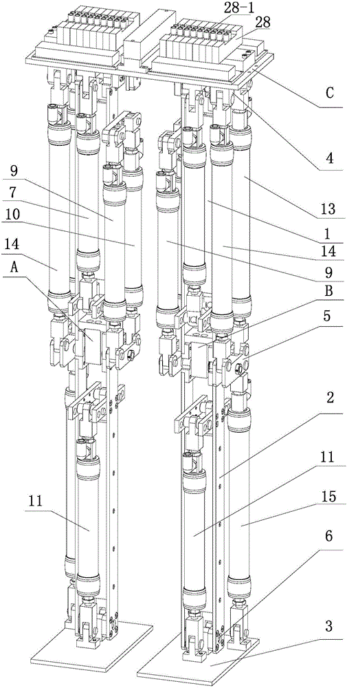
[0010] Specific implementation mode one: combine Figure 1-Figure 6 Illustrate, a kind of biped robot based on pneumatic artificial muscle of this embodiment, it comprises left leg A, right leg B and pelvis C; Left leg A and right leg B respectively comprise thigh 1, calf 2, foot 3, hip Joint 4, knee joint 5 and ankle joint 6; left leg A and right leg B are connected through pelvis C, pelvis 3 is rotationally connected with thigh 1 through hip joint 4, thigh 1 is rotationally connected with calf 2 through knee joint 5, and calf 2 is rotationally connected through knee joint 5 The ankle joint 6 is rotationally connected with the foot 3;

[0011] The left leg A and the right leg B also include nine pneumatic tendons respectively. The nine pneumatic muscles are iliacus 7, gluteus major 8, vastus lateralis 9, biceps femoris 10, tibialis anterior 11, soleus 12, semitendinosus Muscle 13, rectus femoris 14 and gastrocnemius 15;

[0012] Thigh 1 is provided with iliacus 7 , vastus m...

specific Embodiment approach 2

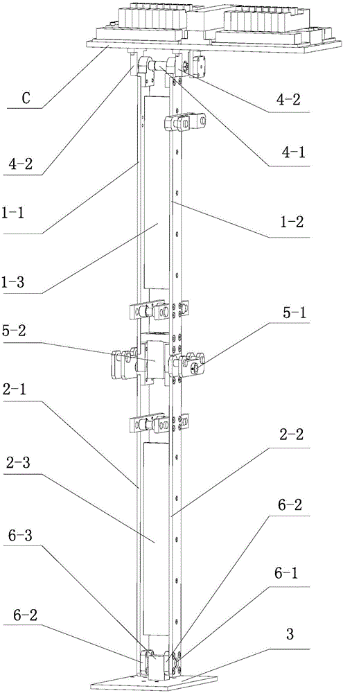
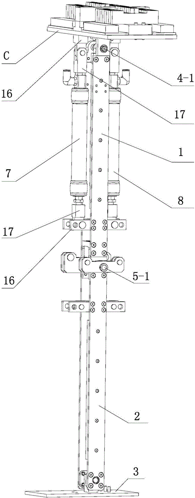
[0015] Specific implementation mode two: combination figure 2 Illustrate, each thigh 1 of present embodiment comprises outer thigh board 1-1, inner thigh board 1-2 and thigh support board 1-3; The thigh support plate 1-3 connected by the two, the hip joint 4 includes two first bearing assemblies 4-2, the two first bearing assemblies 4-1 are installed on the pelvis C respectively, and the hip joint shaft 4-1 is rotated and installed on On the two first bearing assemblies 4-2, the inner thigh plate 1-2 and the outer thigh plate 1-1 are fixedly connected to the hip joint shaft 4-1 respectively. With such arrangement, the outer thigh board and the inner thigh board are connected to the hip joint shaft through the flat key, so that when the hip joint shaft rotates, the thigh is driven to rotate. Others are the same as in the first embodiment.

specific Embodiment approach 3

[0016] Specific implementation mode three: combination figure 2 Illustrate, each calf 2 of present embodiment comprises calf outer plate 2-1, calf inner plate 2-2 and thigh supporting plate 2-3; The calf support plate 2-3 connected by the two, the knee joint 5 includes a second bearing assembly 5-2, the ankle joint 6 includes two third bearing assemblies 6-2, and the second bearing assembly 5-2 is fixed on the outer thigh plate 1-1 and thigh inner board 1-2, the knee joint shaft 5-1 is installed on the second bearing assembly 5-2, and the upper part of the calf outer board 2-1 and the upper part of the lower leg inner board 2-2 are respectively fixed on the On the knee joint shaft 5-1, a third bearing assembly 6-2 is installed on the lower part of the calf outer plate 2-1 and the lower leg inner plate 2-2, and the ankle joint shaft 6-1 is installed on two third bearing assemblies 6 -2, the foot 3 is connected to the ankle joint axis 6-1. In this way, the outer plate of the ...


PUM


Abstract

The invention discloses a biped robot based on pneumatic artificial muscles and relates to biped robots. The biped robot based on the pneumatic artificial muscles aims to solve the problems that an existing active robot is driven through a rigid structure, the system structure is complicated, the flexibility is poor, and the energy efficiency of the existing active robot is low. The biped robot based on the pneumatic artificial muscles comprises a left leg, a right leg and a pelvis. The left leg and the right leg each comprise a thigh, a shank, a foot, a hip joint, a knee joint and an ankle joint. The left leg and the right leg are connected through the pelvis. The pelvis is connected with the thighs in a rotary mode through the hip joints. The thighs are connected with the shanks in a rotary mode through the knee joints. The shanks are connected with the feet in a rotary mode through the ankle joints. The iliac muscles, the gluteus maximus, the vastus lateralis muscles, the biceps femoris muscles, the semitendinous muscles and the rectus femoris muscles are arranged on the thighs. The tibialis anterior muscles, the soleus muscles and the gastrocnemius muscles are arranged on the shanks. The upper ends of the iliac muscles and the upper ends of the gluteus maximus are hinged to the pelvis respectivley. The lower ends of the iliac muscles and the lower ends of the gluteus maximus are hinged to the thighs respectively. The upper ends of the vastus lateralis muscles and the upper ends of the biceps femoris muscles are hinged to the thighs respectively. The biped robot based on the pneumatic artificial muscles belongs to the field of humanoid robots.

Description

technical field [0001] The invention relates to a biped robot and belongs to the field of humanoid robots. Background technique [0002] Humanoid biped robot is a research hotspot in the field of robotics. Biped robot can realize stable walking, running, up and down stairs and other actions. Traditional biped robots, ie active robots, usually use rigid motors and reducers as drive elements, and the control and drive systems are very complex, making the energy efficiency of the robot very low. In view of this situation, the present invention adopts the pneumatic artificial muscle as the driving element of the biped robot. Because the pneumatic artificial muscle has the advantages of suppleness, high power / mass ratio, and similar force / length characteristics to human muscles, the robot’s The joints are flexible, which is beneficial to improve the energy efficiency of the robot. Contents of the invention [0003] The invention aims to solve the problems that the existing ac...

Claims


Application Information

Patent Timeline
IPC IPC(8): B62D57/032
Inventor 臧希喆刘义祥朱延河刘鑫宇王林
Owner HARBIN INST OF TECH
Why Eureka
Try Eureka