
A foamy crude oil three-phase separator

A technology of three-phase separator and separator, which is applied in the direction of refining by centrifugal force, refining by heating/cooling, dehydration/demulsification by mechanical method, etc. It can solve the problems such as poor three-phase separation effect of foaming crude oil, and achieve improvement Dehydration efficiency of crude oil, improvement of separation degree, effect of increasing effect

Active Publication Date: 2016-10-26
PETROCHINA CO LTD
View PDF3 Cites 0 Cited by
  • Summary
  • Abstract
  • Description
  • Claims
  • Application Information

AI Technical Summary

Problems solved by technology

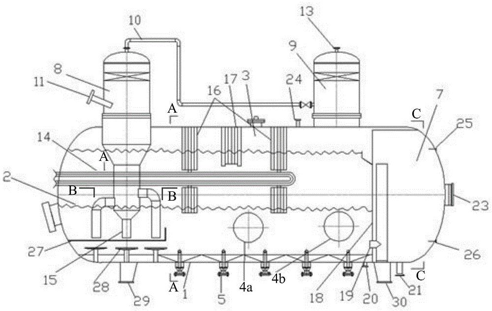
[0004] The invention provides a foamy crude oil three-phase separator to solve the technical problem in the prior art that the three-phase separation effect of foamy crude oil is not good

Method used


Image

  • A foamy crude oil three-phase separator
  • A foamy crude oil three-phase separator
  • A foamy crude oil three-phase separator

Examples


Embodiment Construction

[0062] The invention provides a foamy crude oil three-phase separator to solve the technical problem in the prior art that the three-phase separation effect of the foamy crude oil is not good.

[0063] The technical solution in the embodiment of the present application is to solve the above-mentioned technical problems, and the general idea is as follows:

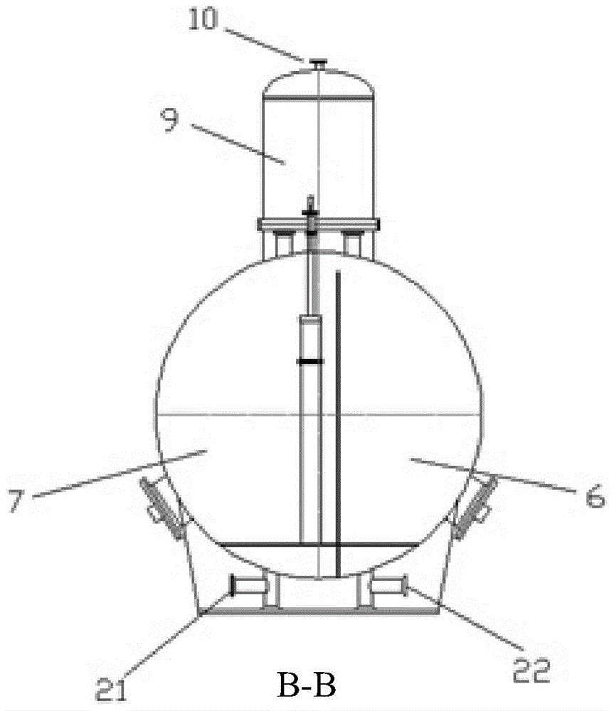
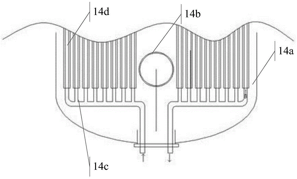
[0064] A foam crude oil three-phase separator is provided, comprising: a tank body; a first support arranged on the first side of the bottom of the tank body; a second support arranged on the second side of the bottom of the tank body, the The first side is opposite to the second side; five sand collection buckets are arranged horizontally between the first support and the second support, and the five sand collection buckets are welded to the tank body and extend into the inside of the tank body; the partition is longitudinally arranged inside the tank body, and divides the tank body into a first tank body space and a secon...


PUM


Abstract

The invention relates to the mechanical field, discloses a three-phase separator for foamed crude oil and aims to solve the technical problem that the three-phase separation effect is poor for foamed crude oil in the prior art. The separator comprises a tank, a first support, a second support, five sand collecting hoppers, a separation plate, an oil outlet pipe, a water outlet pipe, a first mist catcher, a second mist catcher, a connecting pipe, an oil-gas-water inlet pipe, a liquid reducing pipe, a liquid distributing pipe, two sieve plate type defoaming structures, a folded plate type mist catcher and a finned heat exchange defoaming device, wherein the separation plate divides the tank into a first tank space and a second tank space, and the inside of the second tank space is divided into an oil chamber and a water chamber; the liquid reducing pipe comprises a first pipe body, a second pipe body arranged at the bottom of the first pipe body as well as a third pipe body arranged at the bottom of the second pipe body; the finned heat exchange defoaming device penetrates through the two sieve plate type defoaming structures. The technical effects of increasing the oil-gas separation degree and the crude oil dehydration efficiency are realized.

Description

technical field [0001] The invention relates to the mechanical field, in particular to a foamy crude oil three-phase separator. Background technique [0002] In the process of oil field production, the dehydration of conventional crude oil usually adopts the method of gravity sedimentation for three-phase separation of oil, gas and water. Substances and components, they can be adsorbed on the surface of oil-water or gas-liquid, and have a stabilizing effect on liquid droplets or bubbles, resulting in the emulsification and foaming of crude oil. During the dehydration process of crude oil, the dissolved bubbles precipitated from crude oil rise to After the crude oil liquid level, a stable foam layer is formed on the crude oil liquid level, causing a false liquid level in the separator, making it difficult to control the liquid level of the separator, resulting in incomplete oil-water separation, affecting the separation efficiency, and the separated crude oil contains water ...

Claims


Application Information

Patent Timeline
Patent Type & Authority Patents(China)
IPC IPC(8): C10G31/10C10G31/06C10G33/06
Inventor 项勇梁晓亮
Owner PETROCHINA CO LTD
Learn More