A wall and floor tile roller kiln for correcting convective heat transfer of adobe products

A convective heat transfer, wall and floor tile technology, used in the field of roller kilns, can solve the problems of black cores, gas residues, and molten holes in adobe products, and achieve the effects of increasing the speed of the conveyor belt, shortening the overflow time, and improving the quality of finished products.

Inactive Publication Date: 2018-05-29
广东蓝清能源科技有限公司
View PDF6 Cites 0 Cited by
  • Summary
  • Abstract
  • Description
  • Claims
  • Application Information

AI Technical Summary

Problems solved by technology

But at this time, the lower part of the adobe has not yet heated up to the above temperature range. When the temperature of the lower part of the adobe rises to the above temperature range, the organic matter and carbides in the lower part also start to oxidize and decompose, and the generated gas begins to overflow upwards. However, since the liquid phase has already appeared on the upper surface of the adobe, the gas generated by the reaction in the lower part of the adobe cannot quickly overflow from the upper surface, resulting in some gas remaining inside the adobe when it enters the firing stage, resulting in a large amount of gas after leaving the kiln. The adobe products have defects such as black cores, air bubbles, melting holes and dirt absorption, which affect product quality
In response to this problem, in order to allow the gas generated in the oxidation and decomposition reactions of the bricks to have sufficient time to completely overflow from the interior, people will slow down the transmission speed of the conveyor belt, but this will undoubtedly reduce the production rate of the kiln and cause the kiln to production decline

Method used


Image

  • A wall and floor tile roller kiln for correcting convective heat transfer of adobe products
  • A wall and floor tile roller kiln for correcting convective heat transfer of adobe products

Examples


Embodiment Construction

[0013] The present invention will be described in detail below in conjunction with the accompanying drawings.

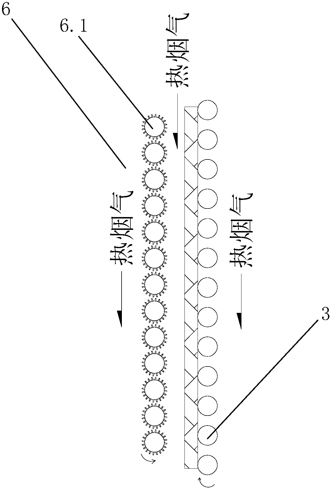
[0014] Such as figure 1 and figure 2 As shown, a roller kiln for wall and floor tiles of the present invention which corrects the convective heat transfer of adobe products includes a kiln body 1, and the inlet end of the kiln body 1 is provided with a smoke exhaust fan 2.1 and a smoke exhaust pipeline 2.2, and the smoke exhaust fan 2.1 and The smoke exhaust pipeline 2.2 constitutes the smoke exhaust box 2. The kiln body 1 is equipped with a conveyor belt 3 composed of several rollers. After the smoke exhaust box 2, several upper burners 4 and lower burners 5 are respectively arranged on the upper and lower sides of the conveyor belt 3, and the lower burners 5 The setting position of the burner is before the setting position of the upper burner 4. Above the conveyor belt 3, between the end of the smoke exhaust box 2 and the upper burner 4, there is a horizontally...


PUM


Abstract

The invention relates to a wall and floor brick roller way kiln for correcting convective heat transfer of a green brick product. The wall and floor brick roller way kiln comprises a kiln body. A smoke exhaust fan and smoke exhaust pipelines are arranged at the inlet end of the kiln body and form a smoke exhaust box body. A conveying belt composed of a plurality of roller bars is arranged in the kiln body. The positions, on the upper side and the lower side of the conveying belt, behind the smoke exhaust box body are each provided with a plurality of upper burners and lower burners. The arrangement positions of the lower burners are in front of the arrangement positions of the upper burners. A turbulent flow mechanism arranged horizontally or obliquely is arranged above the conveying belt and formed by linearly arranging a plurality of impellers. The rotating directions of the impellers are opposite to those of the roller bars of the conveying belt. Each impeller is a roller bar with teeth on the peripheral surface. The turbulent flow mechanism is arranged between the tail end of the smoke exhaust box body and the upper burners, the mounting angle of the turbulent flow mechanism ranges from 0 degree to 45 degrees, and the distance between the turbulent flow mechanism and the conveying belt ranges from 20 mm to 350 mm. The wall and floor brick roller way kiln is good in produced finished product quality and meanwhile high in yield.

Description

technical field [0001] The invention relates to a roller hearth kiln. Background technique [0002] In the production of wall and floor tile roller kilns, the organic matter and low-temperature salt in the bricks are mainly concentrated in the temperature range of 980-1100°C for oxidation and decomposition reactions, and a large amount of CO, CO 2 、H 2 O and other gases, these gases will overflow upward from the upper surface of the brick. At this time, the liquid phase gradually begins to appear on the surface of the brick, and the particles are rearranged tightly and fill the gaps, so that the brick gradually shrinks. However, due to the blocking effect of the conveyor belt on the hot flue gas, the lower part of the adobe cannot fully contact with the hot flue gas, so that the heat absorption speed of the lower part of the adobe will be slower than that of the upper part. When the upper part of the adobe first reaches the above-mentioned temperature range, the organic ma...

Claims


Application Information

Patent Timeline
Patent Type & Authority Patents(China)
IPC IPC(8): F27B9/24F27B9/36F27B9/30
CPCF27B9/2407F27B9/3005F27B9/36
Inventor 温千鸿彭松华
Owner 广东蓝清能源科技有限公司
Why Eureka
Try Eureka