Belt casting machine having adjustable contact length with cast metal slab

a belt casting machine and contact length technology, applied in the field of twin belt casting, can solve the problems of reducing the heat extraction rate of the caster designed to cast foil alloy, requiring a relatively low heat extraction rate, and having a relatively long cavity, so as to prevent any over-cooling effect, reduce the amount of heat being removed, and maintain the effect of continuous throughpu

Active Publication Date: 2007-09-20
NOVELIS INC
View PDF11 Cites 9 Cited by
  • Summary
  • Abstract
  • Description
  • Claims
  • Application Information

AI Technical Summary

Benefits of technology

[0014] Reducing the portion of the cavity in contact with the slab in the above manner significantly reduces the amount of heat being removed from the slab and therefore prevents any over-cooling effect. Where an alloy requiring a lower heat flux for casting is being processed, the tilt mechanism is pivoted so as to bring a greater portion of the casting cavity in contact with the slab, and thus ensure that the slab leaves the casting cavity at substantially the same exit temperature as other metals requiring a higher heat flux. This may require having the entire length of the casting cavity in contact with the slab.
[0015] Thus, embodiments of the present invention provide a casting machine that, for a wide range of metal alloys (e.g. aluminum alloys), can operate at essentially constant throughput while ensuring that the cast slab exiting the caster has a temperature lying within a predetermined range suitable for further rolling to produce a sheet product. This means that parameters can be established for different alloys and exit temperature requirement so that, depending on those requirements, the position of the adjustable portion of the casting region can be set prior to a casting run.
[0016] The fixed portion of the casting cavity preferably converges, most preferably with a convergence of about 0.015% to 0.025% (corresponding to the linear shrinkage of the solidified slab), while the adjustable porti...

Problems solved by technology

As a result, a caster designed to cast foil alloys, requiring a relatively low heat extraction, will have a relatively long cavity.
If the same caster is used with a high heat flux suita...

Method used


Image

  • Belt casting machine having adjustable contact length with cast metal slab
  • Belt casting machine having adjustable contact length with cast metal slab
  • Belt casting machine having adjustable contact length with cast metal slab

Examples


Embodiment Construction

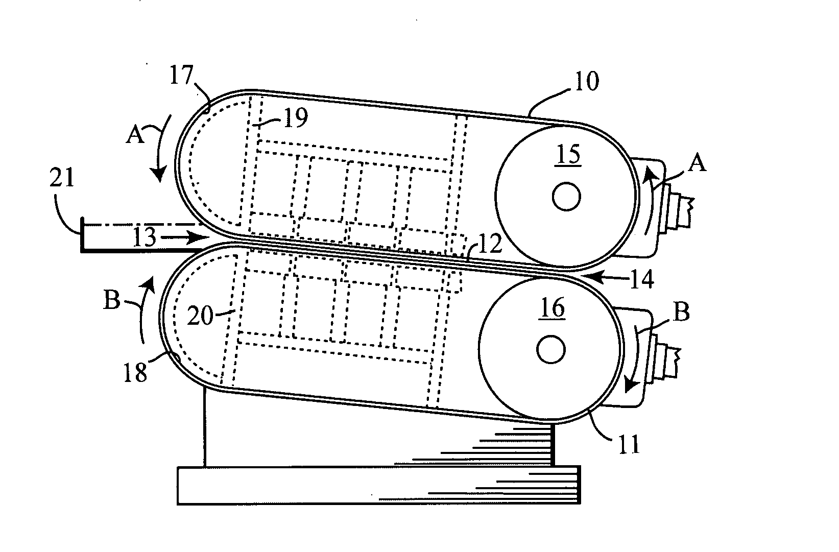
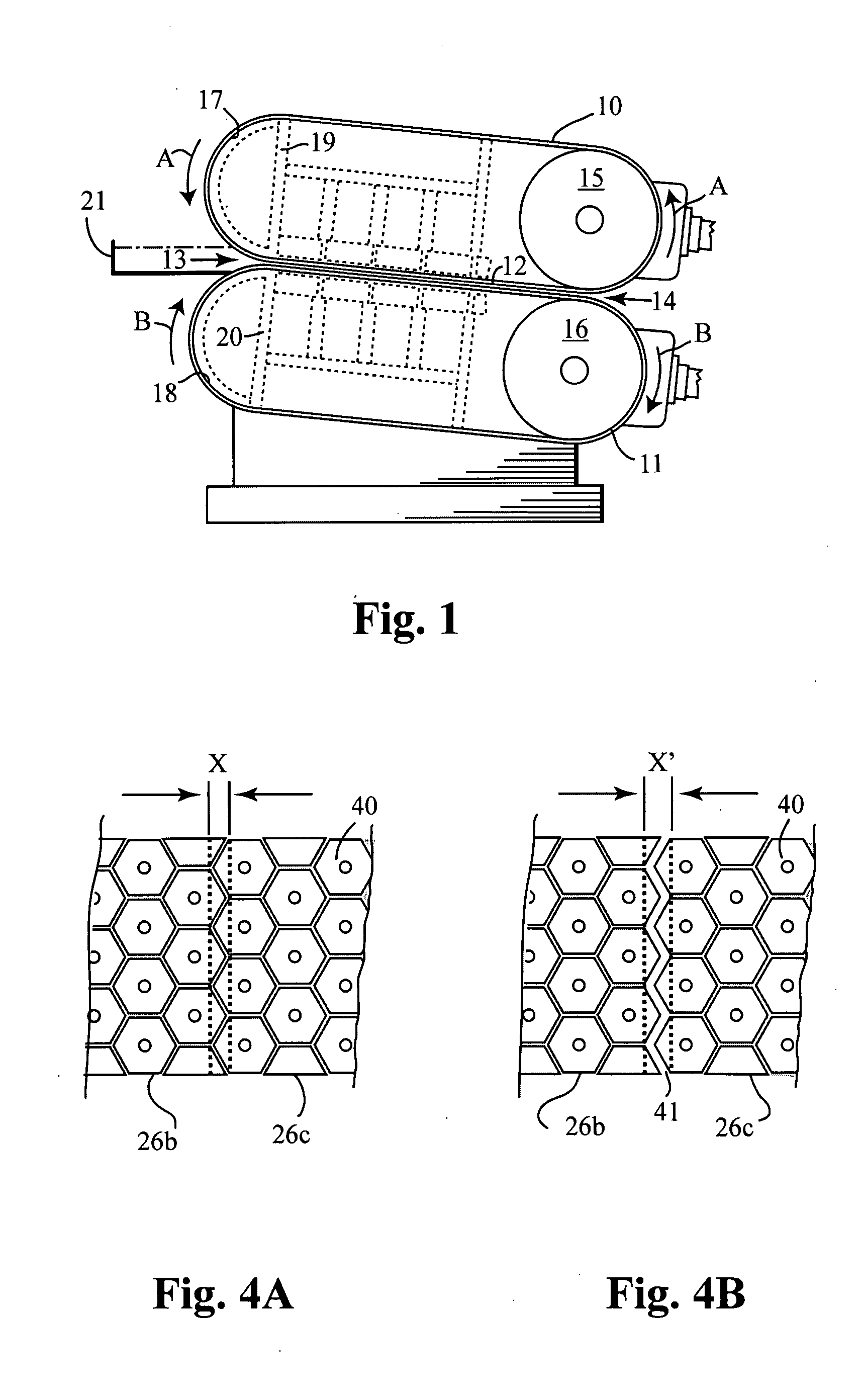
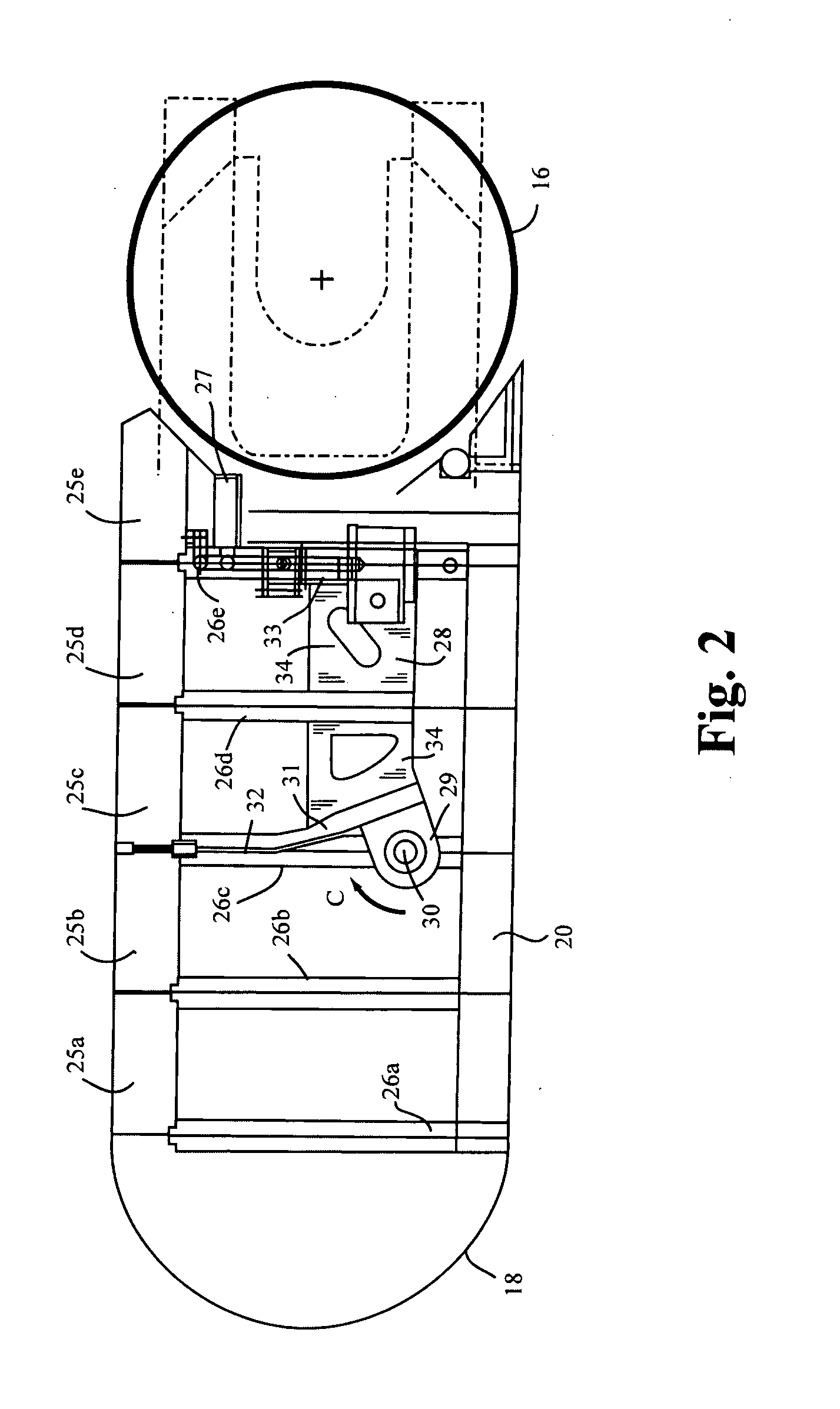
[0022] Referring to the drawings, an example of a basic belt casting machine to which the present invention may be applied is shown in FIG. 1. It includes a pair of resiliently flexible, heat conducing metal bands, forming upper and lower endless belts 10 and 11. These belts travel in looped paths in the directions of arrows A and B so that, in traversing a region where they are close together (i.e. a confronting section of fixed length), the belts define a casting cavity 12 (parallel or slightly converging) extending from a liquid metal entrance end 13 to a solid strip discharge exit end 14. The belts 10 and 11 are respectively driven and carried around by large drive rollers 15 and 16, to return toward the entrance end 13, after passing around curved, liquid-layer bearing structures, respectively shown at 17 and 18. Supporting carriage structures 19 and 20 are provided for the respective belts 10 and 11, while the drive rolls 15 and 16 are appropriately carried and connected for s...


PUM

PropertyMeasurementUnit
Fractionaaaaaaaaaa
Fractionaaaaaaaaaa
Fractionaaaaaaaaaa

Abstract

A twin-belt casting machine for casting metal strip. The machine is provided with a casting cavity which includes an upstream fixed casting region, in which the belts are in fixed convergent paths in contact with the cast slab, and an adjacent downstream portion in which the belts are adjustable between alignment with the fixed convergent paths and non-alignment therewith (being less convergent or divergent). When the adjustable portions of the paths are moved outwardly relative to the fixed convergent paths, the belts separate from the cast slab at differing predetermined points within the casting cavity. By adjusting the downstream portion of the casting cavity in this manner, the casting machine can operate at essentially constant throughput for a wide range of alloys while ensuring that the cast slab exiting the caster has a temperature within a predetermined range suitable for further rolling to produce sheet product.

Description

CROSS-REFERENCE TO RELATED APPLICATIONS [0001] This application claims the priority right of our prior co-pending U.S. provisional patent application Ser. No. 60 / 783,767 filed Mar. 16, 2006.BACKGROUND OF THE INVENTION [0002] (1) Field of the Invention [0003] This invention relates to a process and apparatus for the continuous belt casting of metal strips and, particularly, to the twin-belt casting of metal strips from a variety of molten metals having different cooling requirements and characteristics. [0004] (2) Description of the Related Art [0005] Twin-belt casting of metal strips typically involves the use of a pair of endless belts, usually made of flexible, resilient steel bands or the like, which are driven over suitable rollers and other path defining means, so that they travel together along opposite sides of an elongated narrow space, typically downward-sloping or horizontal, which forms a casting cavity. Molten metal is introduced between the belts in the vicinity of the ...

Claims


Application Information

Patent Timeline
IPC IPC(8): B22D11/06
CPCB22D11/0605B22D11/0654B22D11/168B22D11/0685B22D11/0677B22D11/06B22D21/04B22D11/124
Inventor FITZSIMON, JOHNDESROSIERS, RONALD ROGERGALLERNEAULT, WILLARD MARK TRUMANGATENBY, KEVIN MICHAEL
Owner NOVELIS INC
Why Eureka
Try Eureka