Mud pump piston with pits on surface

A mud pump and pit technology, which is applied to the components of the pumping device for elastic fluid, pump components, variable displacement pump components, etc., can solve the problems of piston wear, piston sealing performance decline, poor lubrication performance, etc. Achieve the effect of improving wear resistance, extending piston life and improving sealing performance

Inactive Publication Date: 2014-11-26
JILIN UNIV
View PDF9 Cites 2 Cited by
  • Summary
  • Abstract
  • Description
  • Claims
  • Application Information

AI Technical Summary

Problems solved by technology

During the high-pressure and high-speed reciprocating motion of the piston, the surface material of the piston cup is worn away and lost, making the diameter of the piston smaller, causing the mud to rush through the friction pair of the cylinder liner and piston, and causing the piston to fail
The direct contact between the piston and the cylinder liner is the piston cup. Due to the poor ability of the current piston cup to store lubricating oil, the lubrication performance of the cylinder liner-piston friction pair is poor, which is also an important cause of serious wear and failure of the piston.
Through the observation during the test, it was found that although the piston did not fail, due to the slight wear of the piston, the sealing performance of the piston decreased, resulting in a decrease in the pressure and flow rate of the drilling fluid discharged, affecting the overall drilling efficiency

Method used


Image

  • Mud pump piston with pits on surface
  • Mud pump piston with pits on surface
  • Mud pump piston with pits on surface

Examples


Embodiment Construction

[0023] The specific content and implementation mode of the present invention will be further described below in conjunction with the accompanying drawings.

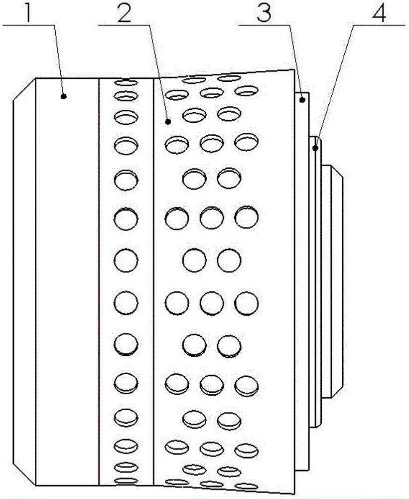
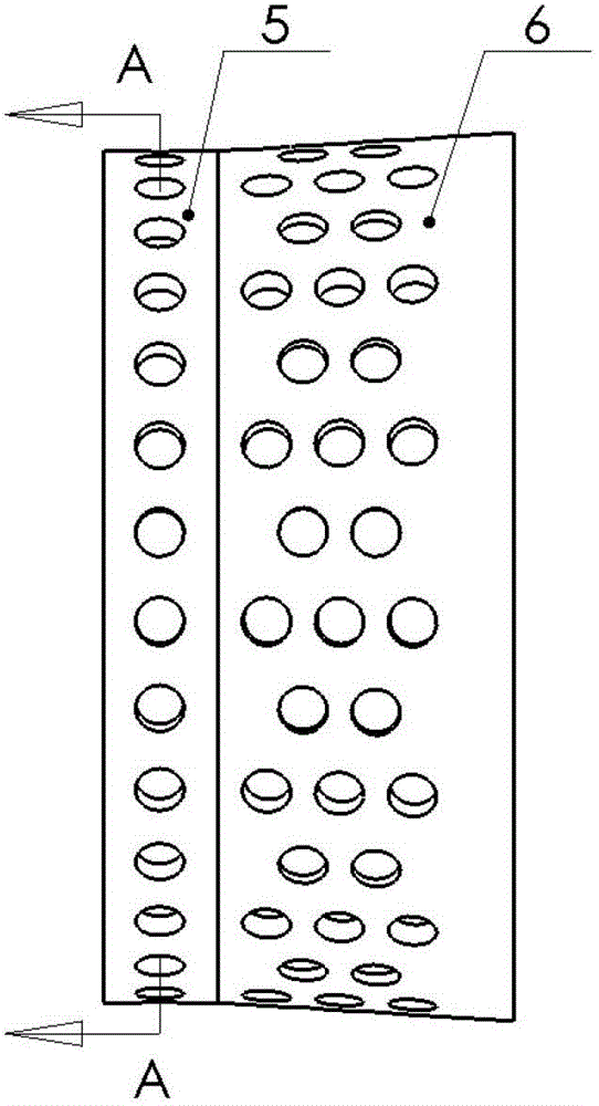
[0024] A mud pump piston with pits on the surface is composed of a piston core 1, a leather cup 2, a pressure plate 3, and a snap ring 4, wherein the leather cup 2 is composed of a nylon mulch ring 5 and a lip rubber 6 bonded together. The leather cup 2 is fixed on the piston core 1 through the pressure plate 3 and the snap ring 4 . The surface of the piston cup 2 of the mud pump has a pit array, and the area of ​​the pit array accounts for 10% to 25% of the surface area of ​​the piston cup 2. The longitudinal section of the pit can be rectangular or arc-shaped. The pit array on the surface of the cup 2 can be formed by one-time die-casting, or can be prepared by reprocessing on the surface of the cup.

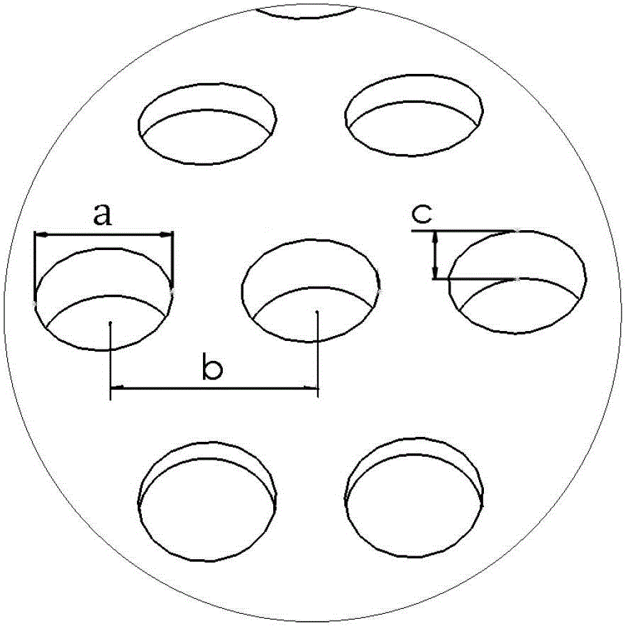
[0025] The dimple diameter a, spacing b, and depth c on the surface of the cup are determined according to the size of...


PUM


Abstract

The invention relates to a mud pump piston with pits on surface. The mud pump piston consists of a piston core (1), a leather cup (2), a press plate (3) and a clamp ring (4), wherein the leather cup (2) is formed by a nylon root protecting ring (5) and lip rubber (6) which are bonded with each other... A pit array is regularly arranged on the surface of the leather cup (2) of the mud pump piston, and the area of the pit array accounts for 10% to 25% of the superficial area of the leather cup (2) of the piston. The diameter (a), space (b) and depth (c) of the pits are set according to the size of the piston, wherein the depth (c) of each pit is generally 0.5 to 1 time the diameter (a) of the pit, the space (b) between the centers of each two adjacent pits is generally 1.2 to 1.8 times the diameter (a) of the pits, an included angle (d) between the center of each two adjacent rows of pits to the circle center of the piston is generally 6 to 12 degrees, and the longitudinal section of each pit is rectangular or circular-arc-shaped. The pits added on the surface of the leather cup of the piston aim to improve the sealing, lubricating and wear-resisting performance of the piston so as to prolong the service time of the piston.

Description

Technical field: [0001] The invention relates to a mud pump piston with pits on the surface. Drilling mud pump pistons used in the exploitation of oil, coal bed methane, oil shale, groundwater, etc. Background technique: [0002] The mud pump is an important part of drilling equipment and the "heart" of the drilling fluid circulation system. When drilling, the mud pump transports high-pressure mud to the downhole to cool the drill bit, carry out rock cutting, and serve as the power fluid for the bottom hole drilling tool to assist the drill bit in drilling. Practice has proved that the cylinder liner and piston group are the most likely to fail during the use of the mud pump. Compared with the cylinder liner, the service life of the piston is lower. [0003] According to the test results, it is found that the failure of the mud pump piston is often caused by severe wear from the lip of the cup to the root of the cup. During the high-pressure and high-speed reciprocating m...

Claims


Application Information

Patent Timeline
Patent Type & Authority Patents(China)
IPC IPC(8): F04B53/14
Inventor 丛茜汝绍锋
Owner JILIN UNIV
Why Eureka
Try Eureka