Improved blast furnace coal injection tank and injection method

A blast furnace coal injection and coal injection tank technology, which is applied to blast furnaces, blast furnace details, blast furnace parts, etc., can solve the problems of large pressure changes in the coal injection tank, fluctuations in injection rate, and long coal charging time, so as to improve the accuracy. and uniformity, reduce consumption and equipment damage, and improve the effect of injection stability

Inactive Publication Date: 2015-12-23
HANGANG GRP HANBAO IRON & STEEL
View PDF4 Cites 2 Cited by
  • Summary
  • Abstract
  • Description
  • Claims
  • Application Information

AI Technical Summary

Problems solved by technology

The quality of pulverized coal fluidization in the coal injection tank determines whether the pulverized coal transportation is smooth, especially the distance from the coal injection tank to the air supply regulator. When the transportation effect is poor, the injection rate will fluctuate greatly, even Stopping coal, affecting the normal smelting of blast furnaces
At present, most enterprises blast furnace coal injection tanks such as figure 1 As shown, it mainly includes the pulverized coal bin and the coal injection tank connected to each other through the connecting pipe. The lower coal valve and the coal inlet valve are respectively installed on the connecting pipe. The large diffuser, medium diffuser and small diffuser are arranged on the top of the coal spraying tank. The coal spraying tank is equipped with a fluidized plate, a fluidized hole at the upper cone, a fluidized bed and a fluidized hole at the bottom in sequence from top to bottom. The upper fluidization hole and the bottom fluidization hole are respectively connected with the upper cone fluidization pipe and the bottom fluidization pipe, and the upper cone fluidization valve and the bottom fluidization valve are installed on the upper cone fluidization pipe and the bottom fluidization pipe Valve, the coal outlet pipe body of the coal injection tank is installed in sequence from left to right with a coal outlet hand valve, a metal soft connection, a coal outlet valve and a coal feed valve. Pressure valve; the coal injection tank with this structure adopts the upper part of the pressurization method, the flow rate of the pressurized gas is large, the coal powder in the coal injection tank is compacted from the upper part, and the bottom fluidization and upper cone fluidization are only opened during injection. , the pulverized coal in the tank is not fully fluidized, and the stability rate of coal injection in the blast furnace cannot be guaranteed; in addition, the coal injection system with this structure has the following disadvantages: (1) During the injection process, the pressure change of the coal injection tank (2) In the direct injection process, due to the easy shedding of materials at the discharge port of the pulverized coal silo, the coal charging time is long, and the pressurization time is forced to be shortened. Affect the fluidization of pulverized coal in the coal injection tank; (3) The distance from the coal outlet of the coal injection tank to the air supply regulator belongs to dense phase transportation, the transportation effect is poor, and the pipeline is easy to block; (4) The powder return pipe is easy to block , affecting the weighing, especially in the process of coal loading, affecting the weighing of another tank of the series, resulting in fluctuations in coal injection rate; (5) The equipment is easy to wear, leak and damage, and the gas energy consumption is large and the waste is serious

Method used


Image

  • Improved blast furnace coal injection tank and injection method
  • Improved blast furnace coal injection tank and injection method
  • Improved blast furnace coal injection tank and injection method

Examples


Embodiment Construction

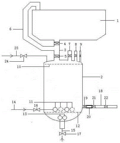
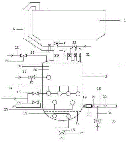
[0021] Figure 2-Figure 3 It shows that an improved blast furnace coal injection tank of the present invention comprises a pulverized coal bin 1 and a coal injection tank 2 communicated with each other through a communication pipe 3, and a lower coal valve 4 and a coal inlet valve 5 are respectively installed on the communication pipe 3. The lower part of the coal valve 4 is connected to a nitrogen purge pipe 31, on which a nitrogen purge valve 32 is installed; between the lower coal valve 4 and the coal inlet valve 5, there is a powder return pipe 6 directly connected to the pulverized coal bin 1, and a powder return pipe 6 is installed Gas filter screen 36; the top of the coal injection tank 2 is provided with a large diffuser 7, a medium diffuser 8 and a small diffuser 9, and the coal injection tank 2 is provided with a fluidization plate 10, a pressure-stabilizing fluidization hole 26, and an upper cone successively from top to bottom. Fluidization holes 11, lower cone flu...


PUM


Abstract

The invention provides an improved blast furnace coal injection tank and an injection method, and belongs to the technical field of blast furnace coal injection. Lower conical part fluidization holes are formed between upper conical part fluidization holes in a coal injection tank body and a fluidized bed, and a pressure-stabilized fluidization hole is formed between the upper conical part fluidization holes and a fluidization plate. The lower portion of a lower coal valve is connected with a nitrogen purging pipe, and a nitrogen purging valve is arranged on the nitrogen purging pipe. An acceleration device is arranged in a metal flexible connector between a coal discharge hand valve and a coal discharge valve. A nitrogen reversely-purging pipe is installed on a coal discharge pipe body between the coal discharge valve and a coal feed valve. A gas filter net is installed on a powder return pipe. Injection achieved through the improved blast furnace coal injection tank includes a diffusing process, a coal loading process, a pressurized fluidization process and an injection pressure-stabilizing control process. By means of the improved blast furnace coal injection tank and the injection method, the problems of insufficient fluidization, uneven coal discharge and an unstable rate of the coal injection tank in the background technology are solved, and the accuracy and the uniformity ratio of coal injection are increased; meanwhile, gas energy consumption and equipment damage are reduced, the blast furnace coal rate is increased indirectly, the coke rate is lowered, the technological process of a coal injection system is improved, and the injection stability is improved.

Description

technical field [0001] The invention relates to an improved blast furnace coal injection tank and an injection method, and belongs to the technical field of blast furnace coal injection. Background technique [0002] Blast furnace coal injection mostly adopts the tank-in-tank non-interval injection mode to ensure that the blast furnace does not stop coaling. The injection time of tank A = the release time of tank B + the coal filling time of tank B + the pressure filling time of tank B + the waiting time of tank B. Accurate and uniform injection of pulverized coal is conducive to stabilizing the operation of the blast furnace and controlling the temperature of the blast furnace. At the same time, it can increase the combustion rate of pulverized coal, increase the coal ratio of the blast furnace, and reduce the coke ratio. The quality of pulverized coal fluidization in the coal injection tank determines whether the pulverized coal transportation is smooth, especially in the ...

Claims


Application Information

Patent Timeline
IPC IPC(8): C21B7/00C21B5/00
Inventor 韩健刘京瑞谢建军冯帅刘志朝黄京昌宋少刚刘占喜
Owner HANGANG GRP HANBAO IRON & STEEL
Why Eureka
Try Eureka