Pushing and supporting device of tunneling machine and construction method

A tunnel boring machine and support device technology, which is applied in tunnels, earthwork drilling, mining equipment, etc., can solve the problems that the strength cannot bear the thrust of 250 tons, and the embedding accuracy of embedded parts is not high, so as to avoid uneven force and step The effect of smooth, safe, reliable and high-precision installation of embedded parts

Active Publication Date: 2015-12-23
CHINA GEZHOUBA (GRP) FIRST ENG CO LTD
View PDF6 Cites 7 Cited by
  • Summary
  • Abstract
  • Description
  • Claims
  • Application Information

AI Technical Summary

Problems solved by technology

The weight of the TBM body is about 600 tons, the traction force required by the supporting facilities and other devices is about 70 tons, and the sliding friction force between the TBM body and the ground track is about 180 tons. Pre-buried support and reaction devices on the road, the embedded parts are not buried with high precision, and their strength cannot withstand the maximum thrust of 250 tons

Method used


Image

  • Pushing and supporting device of tunneling machine and construction method
  • Pushing and supporting device of tunneling machine and construction method
  • Pushing and supporting device of tunneling machine and construction method

Examples


Embodiment 1

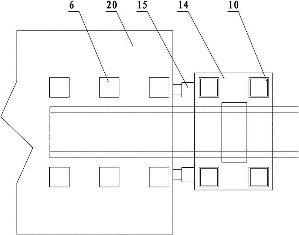
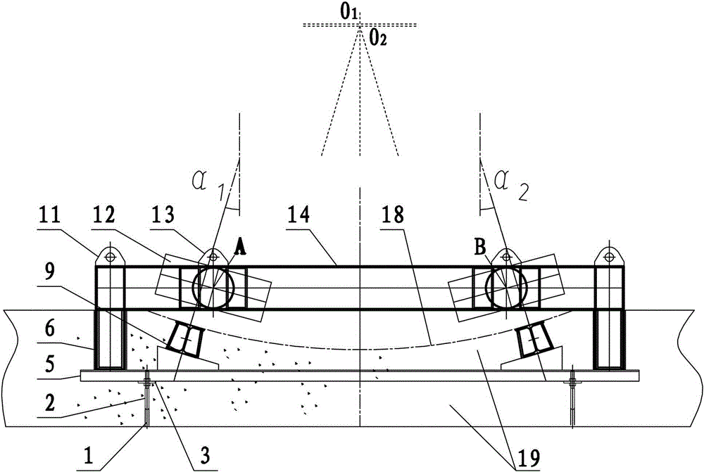
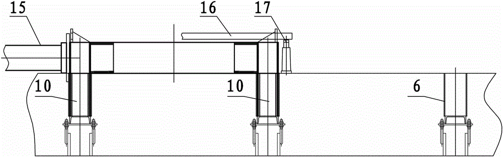
[0037] Such as Figure 1~8 Among them, a tunnel boring machine jacking support device, including a plurality of pre-embedded support anchor hole beams 5, the two ends of the support anchor hole beams 5 are provided with support positioning anchor holes 6; as figure 2 , 3 , Shown in 5, the support positioning anchor hole 6 in this example preferably adopts a square steel pipe.

[0038] Such as figure 1 , 3 Among them, the plurality of supporting anchor hole beams 5 are evenly distributed along the advancing direction of the tunnel boring machine, and at least two upper end surface center vertical beams 5 are located between the supporting positioning anchor holes 6 on the supporting anchor hole beams 5. Lines point to the inclined slide rails 9 of the same center. Such as figure 2 As shown in , of course, those skilled in the art can understand that there may be errors in the actual installation process, such as figure 2 O in 1 and O 2 As shown, try to make O by adju...

Embodiment 2

[0049] This example is the method using the device of Example 1, and the structures not described in this example are the same as those in Example 1.

[0050] Such as Figure 1~8 Shown in, a kind of construction method of tunnel boring machine jacking support device, comprises the following steps:

[0051] 1. Excavate a groove corresponding to the size of the tunnel boring machine 20 on the ground, pour a layer of plain concrete in the groove, and bury a plurality of inserting ribs 1 along the pushing direction and step-by-step pushing distance of the tunnel boring machine. The bolt 2 is welded on the inserted bar 1; the plain concrete refers to the concrete without bars or without reinforced bars.

[0052] 2. Install the steel backing plate 3 on the pre-embedded bolt 2 through the nut 4. In this example, the four corners of the steel backing plate 3 pass through the pre-embedded bolt 2, and are fixed between the upper and lower nuts 4, and are adjusted by the upper and lower...


PUM


Abstract

The invention provides a pushing and supporting device of a tunneling machine and a construction method. The pushing and supporting device of the tunneling machine comprises a plurality of embedded supporting anchor hole beams, at least two inclined slide tracks and a reaction frame; supporting and positioning anchor holes are formed in two ends of each supporting anchor hole beam; reaction frame supporting legs are arranged on the bottom of the reaction frame; and the reaction frame has a frame structure, and is provided with a side surface which is opposite to the end surface of the tail of the tunneling machine and is used for pressing against an auxiliary pushing oil cylinder. The construction method comprises the following steps of (1) welding an embedded bolt on a joint bar; (2) mounting a steel cushion on the embedded bolt through a nut; and (3) mounting the supporting anchor hole beams, the supporting and positioning anchor holes and the slide tracks on the steel cushion, placing the auxiliary hydraulic oil cylinder between the tunneling machine and the reaction frame, and jacking by a stepping stroke. By the steps, the tunneling machine is pushed to walk when beginning to enter a hole. By the pushing and supporting device of the tunneling machine and the construction method, hundreds of tons of stepping thrust can be ensured, and the circumstance that a slide way structure is damaged due to uneven stress can be avoided.

Description

[0001] This application is a divisional application of a patent application entitled "Tunnel boring machine stepping jacking support device and construction method", the application date is November 13, 2013, and the application number is "2013105619687". technical field [0002] The invention relates to the field of tunnel boring machine construction, in particular to a stepping jacking support device and a construction method for tunnel boring machines starting to enter holes. Background technique [0003] Railways, highways, large-scale water conservancy projects, etc. usually need to be constructed in rocky mountains, which are composed of rocks with different softness, hardness and bedding. As the scale of the project increases, the construction speed is required to be accelerated, and many of them have a length greater than 6Km and a cross-section greater than 80m 2 The tunnels are no longer suitable for extensive drilling and blasting construction. In order to speed ...

Claims


Application Information

Patent Timeline
Patent Type & Authority Applications(China)
IPC IPC(8): E21D9/00
Inventor 常国阁周继红赵志忠张诗云余祥忠雷艳兵倪四平崔玉松柳振杰尹方辉
Owner CHINA GEZHOUBA (GRP) FIRST ENG CO LTD
Why Eureka
Try Eureka