Self-coupling type through-flow submersible electric pump

A submersible electric pump and through-flow technology, which is applied to non-variable pumps, parts of pumping devices for elastic fluids, pumps, etc., can solve the problems of increasing the force of civil structures, complicated installation process, and easy water leakage. , to achieve the effect of strengthening operation management, improving adaptability and increasing stability

Active Publication Date: 2015-12-23
TIANJIN GANQUAN GROUP
View PDF6 Cites 3 Cited by
  • Summary
  • Abstract
  • Description
  • Claims
  • Application Information

AI Technical Summary

Problems solved by technology

The disadvantages of this kind of full-through submersible pump in the prior art: ①The installation process is more complicated, and the pump has to be inclined 2-5° when entering the guide rail, which is easy to cause unstable lifting or the outer edge of the guide vane body rubs against the guide rail. The installation cannot be completed at one time; ②When the full-flow submersible pump enters the guide rail and is put into the working position, the O-shaped rubber sealing ring is easily cut, which will make the steel outlet of the guide vane body and the water inlet end of the embedded pipe In contact with steel, the seal is not tight, and it is easy to leak; ③The self-coupling hook assembly and the outlet flow channel are pre-buried on the water retaining wall. Moment, finally acts on the facade of the dam, increasing the force of the civil structure

Method used


Image

  • Self-coupling type through-flow submersible electric pump
  • Self-coupling type through-flow submersible electric pump
  • Self-coupling type through-flow submersible electric pump

Examples


Embodiment

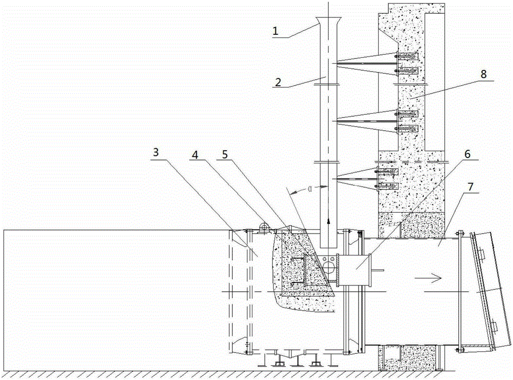
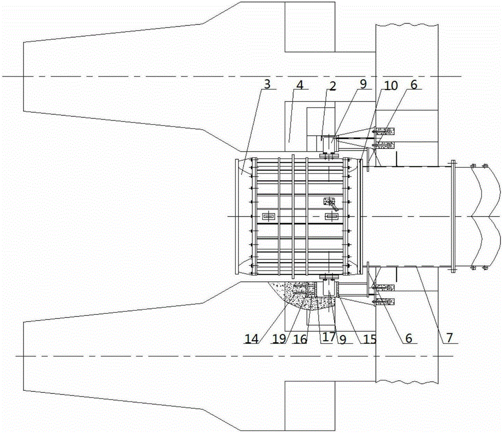
[0025] combine figure 1 and Figure 4 Two sets of symmetrical guide rod assemblies 9 are arranged on both sides of the water outlet of the full-through-flow submersible electric pump 3, and the guide rod assemblies 9 are welded into a whole with the stuffy cover 11, the cylinder 12 and the small bottom plate 13.

[0026] combine Figure 5 , the guide pendant 5 is to weld the thrust slope 17, the bottom plate 18 and a partition plate 15 into a whole, so that the bottom plate 18 and the partition plate 15 are vertical, and the angle formed by the thrust slope 17 and the bottom plate 18 is 180°-α±1° , and ensure that the guide rod assembly 9 slowly descends along the thrust slope 17 until the outlet flange surface of the full-flow submersible pump 3 completely coincides with the water inlet flange surface of the embedded pipe 7 during the coupling process, and the guide rod assembly 9 There is also a sufficient vertical safety distance between the bottom of the cylinder 12 and ...


PUM


Abstract

A self-coupling type through-flow submersible electric pump comprises a through-flow submersible electric pump body, a concrete separation pier and a retention wall. The retention wall is provided with guide rail assemblies extending in the same direction as the retention wall, an embedded pipe is arranged on the bottom of the retention wall, and the concrete separation pier is arranged vertical to the bottom end of the retention wall. The through-flow submersible electric pump body is provided with a guide rod assembly. Locating frames are symmetrically arranged on the two sides of the embedded pipe, and a guiding suspension part is arranged at the tail end of each locating frame. A trapezoid cloth-inserted O-shaped rubber seal ring is arranged on the flange surface of the water outlet end of the through-flow submersible electric pump body. The tail ends of the two guide rail assemblies are located on the top of the integrated body formed by the locating frames, the guiding suspension parts and the embedded pipe. The self-coupling type through-flow submersible electric pump has the advantages that the stability of self-coupling sealing is improved, it can be fast completed to lift and wash the pump and prevent the pump from being rusted during the operation interval period when water taking stops, and operation management can be reinforced to improve the adaptability and the reliability and prolong the service life.

Description

1. Technical field [0001] The invention relates to a full-through-flow submersible electric pump device, in particular to a self-coupling full-through-flow submersible electric pump. 2. Background technology [0002] The general installation method of the full-through submersible pump is to set two symmetrical coupling seats at the outlet end of the pump, and set an auto-coupling hook assembly under the vertical guide rail. The auto-coupling hook assembly is integrated with the outlet flow channel. The water outlet end of the guide vane body is provided with an annular sealing rubber ring. The disadvantages of this kind of full-through submersible pump in the prior art: ①The installation process is more complicated, and the pump has to be inclined 2-5° when entering the guide rail, which is easy to cause unstable lifting or the outer edge of the guide vane body rubs against the guide rail. The installation cannot be completed at one time; ②When the full-flow submersible pum...

Claims


Application Information

Patent Timeline
Patent Type & Authority Applications(China)
IPC IPC(8): F04D13/08F04D29/62F04D29/08
Inventor 马恩成马凤景孙岩岩陈大为陈竑皓耿少杰柴秀发叶丽珍邓悌康
Owner TIANJIN GANQUAN GROUP
Why Eureka
Try Eureka