Reaction cup loading system for automatically conveying reaction cups to analysis device

An analysis device and loading system technology, applied in the direction of analysis materials, instruments, etc., can solve the problems of high failure rate, high cost, and many modules, and achieve the effect of simple operation control, reduced operation cost, and compact overall structure

Inactive Publication Date: 2015-12-23
SYSCAN MEDICAL TECH SUZHOU
View PDF5 Cites 21 Cited by
  • Summary
  • Abstract
  • Description
  • Claims
  • Application Information

AI Technical Summary

Problems solved by technology

This system uses multiple pneumatic components, chain transmission, etc., so the system has complex problems, high failure rate, many modules, the whole device occupies a lot of space, and the cost is high.

Method used


Image

  • Reaction cup loading system for automatically conveying reaction cups to analysis device
  • Reaction cup loading system for automatically conveying reaction cups to analysis device
  • Reaction cup loading system for automatically conveying reaction cups to analysis device

Examples


Embodiment 1

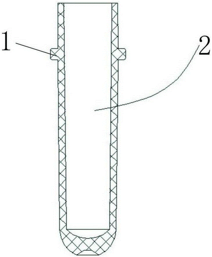
[0039] like figure 1 As shown, the structure of cuvette 2 widely used in current biological sample analysis system is provided with flanges 1 on both sides of the cup body.

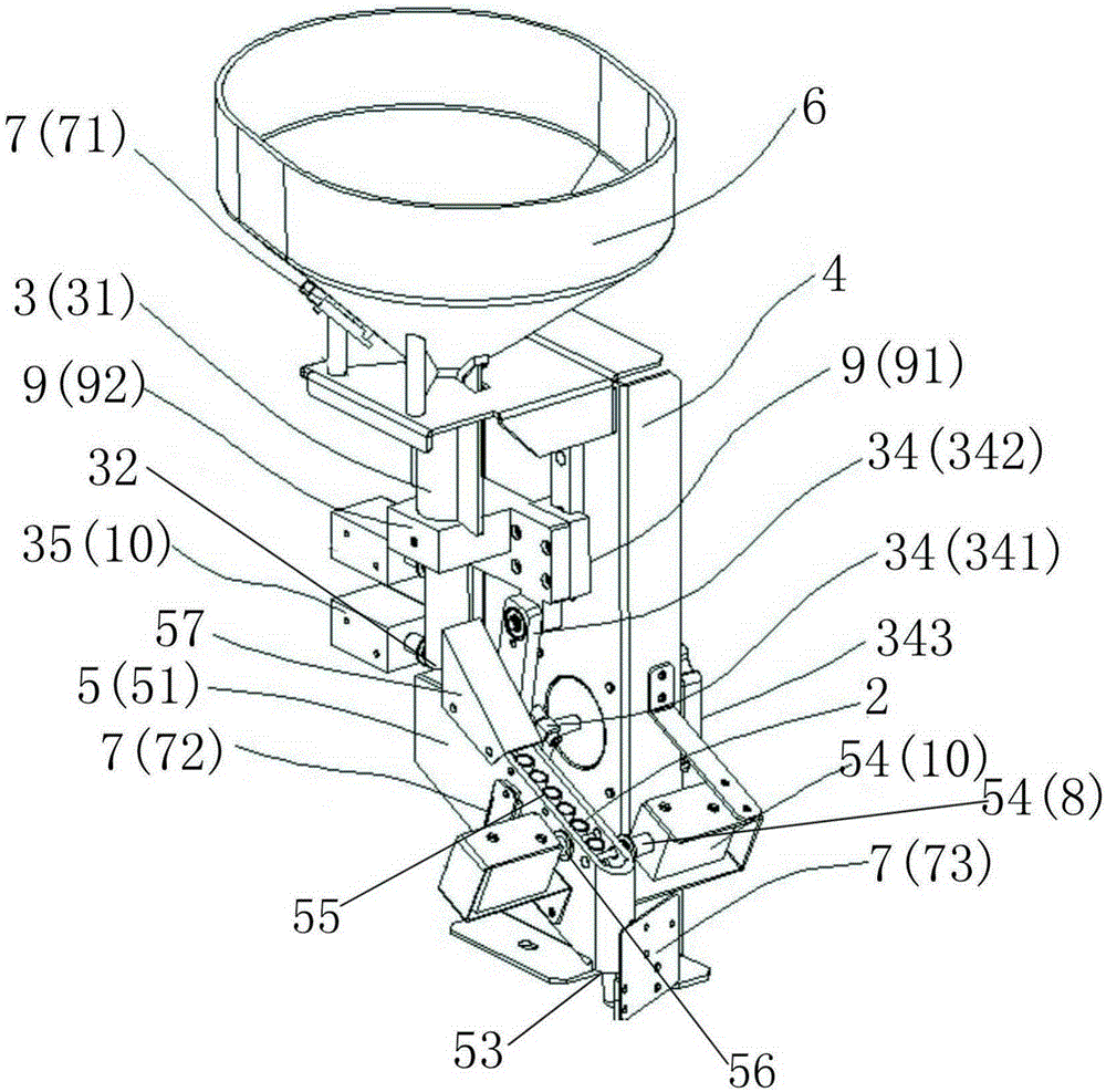
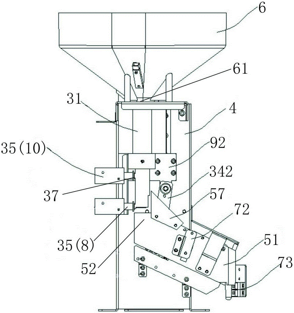
[0040] like figure 2 , 3 , 4, 5, and 6, this embodiment discloses a cuvette loading system for automatically transferring cuvettes for an analysis device, including a frame 4, fixed on the frame 4, and feeding along the cuvette The cup storage bin 6, the cup taking mechanism 3 and the cup feeding mechanism 5 arranged in sequence in the direction, the batch storage in the cup storage bin 6 is like figure 1 In the cuvette 2 shown, the cup fetching mechanism 3 automatically takes the cup from the cup storage bin 6 to the cup feeding mechanism 5, and the cup feeding mechanism 5 automatically feeds the cuvette 2 into the target hole of the biological sample analysis system to complete the reaction. Automatic feeding process for Cup 2.

[0041] Wherein, the storage cup bin 6 is a funnel-shaped structure, a...

Embodiment 2

[0052] like Figure 7 As shown, the second structure of the driver is provided in this embodiment, which includes a first pulley 344 and a second pulley 345 that are rotatably connected by a belt 346, and a motor 343 that drives the first pulley to rotate 344. The fixed The block 92 is fixed on said belt 346 . The motor 343 drives the first pulley 344 to rotate and drive the belt 346 to move up and down, drive the fixed block 92 fixed on the belt 346 to move up and down in the guide rail 91, and finally realize the catheter 31 fixed on the fixed block 92 to move up and down. The driver in the second embodiment can also realize the vertical movement of the conduit 31 to complete the action of taking the cup. Of course, the driver structure of the present invention includes but is not limited to the above two structures.


PUM


Abstract

The invention provides a reaction cup loading system for automatically conveying reaction cups to an analysis device. The reaction cup loading system comprises a rack, as well as a cup storage cabin, a cup fetching mechanism and a cup conveying mechanism which are fixedly arranged on the rack and are arranged in sequence along a conveying direction of the reaction cups, wherein a cup outlet is formed in the bottom of the cup storage cabin; the cup fetching mechanism comprises a guide pipe, a driver for driving the guide pope to hoist to enable the guide pipe to stretch into the cup storage cabin from the cup outlet to take the cups, and a first mechanical switch for controlling the reaction cups in the guide pipe to fall off one by one from a first outlet; the cup conveying mechanism comprises a slide groove and a second mechanical switch for controlling the reaction cups in the slide groove to slide out one by one from a second outlet; the reaction cup loading system further comprises a cup detection mechanism arranged on the cup fetching mechanism and/or the cup conveying mechanism. A reaction cup automatic conveying device provides guarantees to full-automatic operation of a biological sample analysis system, has a compact whole structure, is simple to operate and control, has low operation fault rate and is accurate and reliable to convey; the device can be continuously operated for a long time with the matching of the detection mechanism, so that the conveying efficiency is improved and the operation cost is reduced.

Description

technical field [0001] The invention belongs to the technical field of medical testing equipment, and relates to a supporting device for a biological sample analysis system, in particular to a cuvette loading system for automatically transferring cuvettes for an analysis device. Background technique [0002] As the automation degree of the analysis device and the requirements for the test speed are getting higher and higher, an automatic loading system is required to provide the analyzer with the cuvettes required for the test. A cuvette system capable of automatically providing an analysis device with testing requirements has been documented in public documents, such as US2002106305A1. This patent provides a loading device for automatically transporting cuvettes, which includes a storage bin for storing cuvettes, a transmission chain with hooks, and a cuvette guiding mechanism. The storage compartment stores a certain number of cuvettes. The transmission chain with hooks i...

Claims


Application Information

Patent Timeline
Patent Type & Authority Applications(China)
IPC IPC(8): G01N35/00
Inventor 吴武彬
Owner SYSCAN MEDICAL TECH SUZHOU
Why Eureka
Try Eureka