Supercharge Your Innovation With Domain-Expert AI Agents!

Current detection circuit for DC-DC converter

A technology of current detection circuit and DC converter, applied in the direction of measuring current/voltage, instruments, measuring devices, etc., can solve the problems of complex design, system disorder, performance affecting the control accuracy and efficiency of the converter system, etc., to achieve accurate Detection, the effect of obvious advantages

Active Publication Date: 2018-12-07
SHANGHAI BEILING
View PDF5 Cites 0 Cited by
  • Summary
  • Abstract
  • Description
  • Claims
  • Application Information

AI Technical Summary

Problems solved by technology

[0005] In the DC-DC converter, current sampling and detection is a key module, and its performance affects the control accuracy and efficiency of the entire converter system. If the current detection deviation is large, it may even cause system disorder
[0006] At present, the existing current detection methods are divided into two categories. One is to use resistors to sample current. The disadvantage is that the resistance value of the resistors is demanding, it is not easy to implement, and the sampling signal is easily disturbed; the other is to use high-speed operational amplifiers. Sampling current, the disadvantage is that the design is complex and the cost is large

Method used


Image

  • Current detection circuit for DC-DC converter
  • Current detection circuit for DC-DC converter
  • Current detection circuit for DC-DC converter

Examples


Embodiment Construction

[0016] The current detection circuit for the DC-DC converter of the present invention will be further described in detail below in conjunction with the drawings and specific embodiments, but it is not intended to limit the present invention.

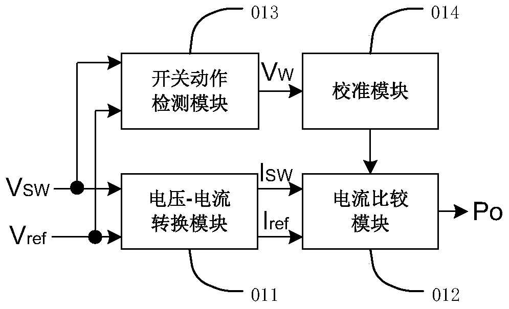
[0017] Such as figure 2 Shown is a schematic structural diagram of a current detection circuit for a DC-DC converter of the present invention. The current detection circuit for a DC-DC converter of the present invention includes a voltage-current conversion module 011 and a current comparison module 012 .

[0018] Wherein, the voltage-current conversion module 011 has two input terminals, one of which is connected to the node SW between the high-side switching tube HS and the low-side switching tube HS of the DC-DC converter to receive the first voltage signal Vsw, and the other One input terminal is connected to the reference voltage terminal to receive the second voltage signal Vref. The voltage-current conversion module 011 convert...


PUM


Abstract

The invention provides a current detection circuit used for a DC-DC converter. The current detection circuit includes a voltage-current conversion module and a current comparison module, wherein the voltage-current conversion module has two input ends, one of the input ends is connected to a node between a high-end switching tube and a low-end switching tube of the DC-DC converter to receive a first voltage signal, the other input end is connected to a reference voltage end to receive a second voltage signal, and the voltage-current conversion module converts the first and second voltage signals to first and second current signals to be output; and the current comparison module is connected to an output end of the voltage-current conversion module to receive the first and second current signals, compares the magnitude of the first and second current signals and outputs a comparison result. Detection of output current can be realized without an extra sampling resistor, and low power consumption can be maintained when large current is output.

Description

technical field [0001] The invention relates to a current detection circuit, in particular to a current detection circuit for a DC-DC converter. Background technique [0002] The DC-DC converter 10 is used to provide power to electronic equipment, and is an indispensable power converter in electronic circuits. Such as figure 1 As shown, it uses the energy storage characteristics of the inductor Lo and the capacitor Co to periodically transfer the input power energy to the output, while only consuming a very small part of power consumption. [0003] Usually, the DC-DC converter uses passive devices (such as resistors) as feedback components, and maintains the stability of the output voltage by setting different feedback coefficients, and controls the current by detecting the output current through the current detection circuit. [0004] The basic structure of DC-DC converter 10 is as figure 1 As shown, it includes a pair of power switches (that is, a high-side switch QH an...

Claims


Application Information

Patent Timeline
Patent Type & Authority Patents(China)
IPC IPC(8): G01R19/165
Inventor 孙彪陈方雄谢雪松陶园林常祥岭赵海亮
Owner SHANGHAI BEILING
Features
  • R&D
  • Intellectual Property
  • Life Sciences
  • Materials
  • Tech Scout
  • Unparalleled Data Quality
  • Higher Quality Content
  • 60% Fewer Hallucinations
Learn More