LED display

An LED display and display technology, which is applied to instruments, optics, optical components, etc., can solve the problems of blurred stereoscopic images and the influence of cylindrical array lenses on the manufacturing yield of naked-eye stereoscopic displays, and achieve the effect of improving resolution.

Inactive Publication Date: 2015-12-23
AU OPTRONICS CORP
View PDF0 Cites 14 Cited by
  • Summary
  • Abstract
  • Description
  • Claims
  • Application Information

AI Technical Summary

Problems solved by technology

However, the yield rate of the display panel, the yield rate of the polarization switching panel, the yield rate of the lenticular array lens, etc. will affect the manufacturing yield rate of the naked-eye stereoscopic display
Furthermore, the lenticular array lens must be precisely aligned with the liquid crystal panel, and the manufacturing error on the lens will cause the light to scatter and cause the three-dimensional image to be blurred

Method used


Image

  • LED display
  • LED display
  • LED display

Examples


Embodiment approach

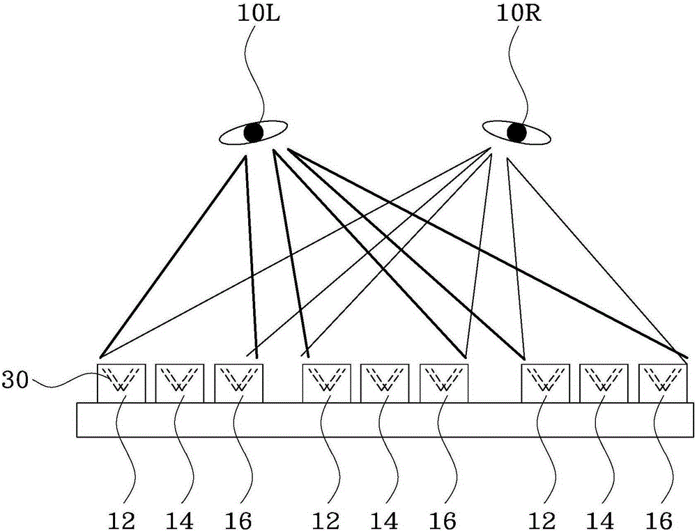
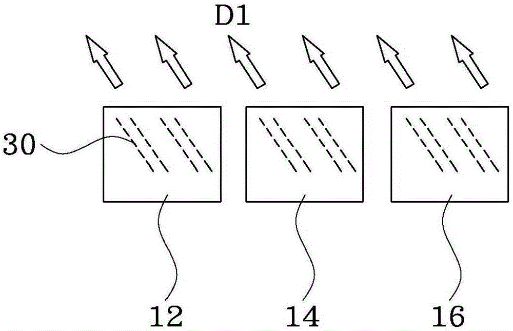
[0028] Figure 1A A schematic structural diagram of an LED display for stereoscopic image display according to the first embodiment of the present invention is shown. Figure 1B show Figure 1A An exemplary embodiment of the light exit angle of the light waveguide in the LED display of the present invention.

[0029] refer to Figure 1A , In this embodiment, the LED display for stereoscopic image display of the present invention includes a plurality of pixels, and each pixel has a red sub-pixel, a green sub-pixel and a blue sub-pixel. Moreover, the red sub-pixel, the green sub-pixel and the blue sub-pixel respectively use LED light sources of different colors, for example, the red sub-pixel uses a red LED light source 12, the green sub-pixel uses a green LED light source 14, and the blue sub-pixel uses a blue LED light source. light source 16. The LED light sources 12 , 14 and 16 of different colors respectively pass through a waveguide 30 to form light waves with two light e...


PUM


Abstract

The invention provides an LED display. The LED display comprises a plurality of pixels. Each pixel comprises a red sub-pixel, a green sub-pixel and a blue sub-pixel, wherein LED light sources with different colors are respectively used for the red sub-pixel, the green sub-pixel and the blue sub-pixel. Furthermore the LED light sources with different colors form two emergent light waves with two emergent angles through a waveguide. Compared with the prior art, the LED display is advantageous in that the trouble in realizing precise alignment between an outer cylindrical array lens and a panel in a process can be saved. Furthermore, in the LED display according to the invention, each sub-pixel generates emergent light waves with different wavelengths through cooperation of an independent LED light source and different light emitting layers, thereby improving the resolution of a three-dimensional image. Furthermore the independent LED light source in each sub-pixel can realize different light emitting angles and can be used for generating the three-dimensional images with high brightness and high resolution.

Description

technical field [0001] The invention relates to a display, in particular to an LED display. Background technique [0002] In a single micro light emitting diode (MicroLED), it often has stacked red emission layer (Reemission layer), green emission layer (Green emission layer) and blue emission layer (Blue emission layer), each light emitting layer has its own vertical waveguide (vertical waveguide) ). Controlled by the electrodes connected to the surface, the light source of the light-emitting layer can be sent out from the light waveguide. In this way, each pixel in the display can generate a light source output with high brightness and better collimation. In addition, each pixel can be designed with a light source with three primary colors of R / G / B, allowing the display to achieve high-resolution and 3D display effects. [0003] In recent years, with the maturity of display technology, the improvement of image dynamic effect, further improvement of color expression and ...

Claims


Application Information

Patent Timeline
Patent Type & Authority Applications(China)
IPC IPC(8): G09F9/33G02B27/22
CPCG02B30/27G09F9/33
Inventor 李和政刘康弘罗国隆杨文玮吴宗典林宗毅
Owner AU OPTRONICS CORP
Why Eureka
Try Eureka