Shifting register unit and driving method thereof, grid driving circuit and display device

A shift register and drive signal technology, which is applied in static memory, digital memory information, instruments, etc., can solve the problem of large layout area of ​​shift register units

Pending Publication Date: 2015-12-23
BOE TECH GRP CO LTD +1
View PDF7 Cites 6 Cited by
  • Summary
  • Abstract
  • Description
  • Claims
  • Application Information

AI Technical Summary

Problems solved by technology

[0005] The enhanced reset control module in the prior art is generally composed of multiple tr

Method used


Image

  • Shifting register unit and driving method thereof, grid driving circuit and display device
  • Shifting register unit and driving method thereof, grid driving circuit and display device
  • Shifting register unit and driving method thereof, grid driving circuit and display device

Examples


Embodiment Construction

[0044] The specific implementation manners of the present invention will be further described below in conjunction with the drawings and examples. The following examples are only used to illustrate the technical solution of the present invention more clearly, but not to limit the protection scope of the present invention.

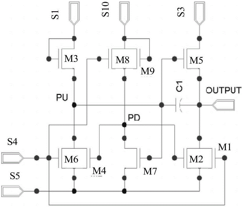
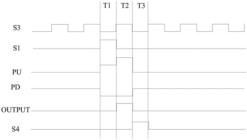
[0045] The structure of an existing shift register unit can refer to figure 1 , including a total of 9 N-type transistors M1-M9 and a capacitor C1, and has multiple input terminals S3, S10, S1, S4 and S5, for figure 1 The driving process of the shift register unit in can refer to figure 2 , during the whole driving process, a clock signal is applied to the input terminal S3, a high level is applied to the input terminal S10, and a low level is applied to the S5; a high level is applied to the other input terminals S1 and S4 at different stages. Level pulse signal, specifically:

[0046] In the first stage T1, a pulse signal is applied to the input termina...


PUM


Abstract

The invention provides a shifting register unit and a driving method thereof, a grid driving circuit and a display device. The shifting register unit comprises an input module, an output control module, a reset module, a reinforced reset module and an energy storage module; the first end of the energy storage module is connected with a first node; the output control module is suitable for outputting a driving signal through a driving signal output end when the level of the first node is a first level; the reinforced reset module is connected with the first node and a sixth input end, and is suitable for setting the voltage of the first node as voltage input by the sixth input end when the first node is at a second level and the input module is turned off. According to the shifting register unit provided by the invention, reinforced reset on the first node can be completed on the premise that a reinforced reset control module is not installed; compared with the shifting register unit which needs to install the reinforced reset control module in the prior art, the shifting register unit disclosed by the invention has the advantages that the layout area is reduced, and the side of the display device is helped to be narrowed.

Description

technical field [0001] The present invention relates to the field of display technology, in particular to a shift register unit, a driving method thereof, a gate driving circuit and a display device. Background technique [0002] With the continuous development of liquid crystal displays, high resolution and narrow bezels have become the development trend of liquid crystal displays, and the application of gate shift registers in display panels is one of the important methods to achieve narrow bezels and high resolution. [0003] The driver of TFT-LCD (ThinFilmTransistor-LiquidCrystalDisplay Thin Film Field Effect Transistor-Liquid Crystal Display) mainly includes a gate drive circuit and a data drive circuit, and the gate drive circuit is mainly composed of multi-stage shift register units and signals connected to each shift register unit The shift register unit of each stage is connected to a gate line, and the pixel TFT is driven by row-by-row scanning through the output d...

Claims


Application Information

Patent Timeline
IPC IPC(8): G11C19/28G09G3/32G02F1/1333
CPCG11C19/28G09G2230/00G09G3/3677G09G2300/0408G09G2310/0286G09G3/36G02F1/1333G09G3/2096G09G3/32G11C19/287
Inventor 于海峰黄海琴王俊伟
Owner BOE TECH GRP CO LTD
Why Eureka
Try Eureka