Air adjusting and heat dissipating self-cleaning transformation cabinet

A self-cleaning, transformer cabinet technology, applied in the substation/distribution device housing, substation/switch layout details, and substation/switchgear cooling/ventilation, etc., can solve the problem of dust, hidden safety hazards, and low cooling and heat dissipation efficiency And other issues

Inactive Publication Date: 2015-12-23
STATE GRID CORP OF CHINA +2
View PDF6 Cites 8 Cited by
  • Summary
  • Abstract
  • Description
  • Claims
  • Application Information

AI Technical Summary

Problems solved by technology

At present, the heat dissipation method and structure of the electrical components in the transformer cabinet have the following defects: 1. Since the transformer cabinets are generally high in height, vertical ventilation is adopted, the air path is long, and the cold air at the end of the air path has been blocked. Heating, so the temperature in the transformer cabinet is still high, and the heat dissipation effect is poor, resulting in shortened service life of electrical components; 2. There is more dust at the air inlet of the air path, so that the wind entering the transformer cabinet carries more dust; 3. 1. After the electrical components are used for a long time, dust is easy to accumulate in the depressions and irregular protrusions of the electrical components, which reduces the service life of the electrical components and forms a safety hazard (possibly causing a short circuit); 4. The air volume of the air circuit is not adjusted. Mechanism, large energy consumption, low cooling efficiency

Method used


Image

  • Air adjusting and heat dissipating self-cleaning transformation cabinet
  • Air adjusting and heat dissipating self-cleaning transformation cabinet
  • Air adjusting and heat dissipating self-cleaning transformation cabinet

Examples


Embodiment Construction

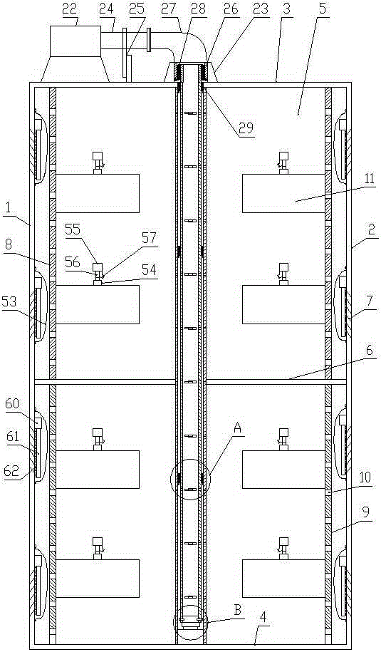
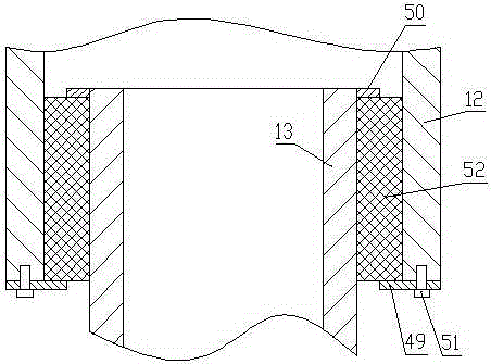
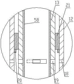
[0028] Such as Figure 1-Figure 7 As shown, the air conditioning and heat dissipation self-cleaning transformer cabinet of the present invention comprises a cabinet in the shape of a cuboid, and the cabinet consists of a left side panel 1, a right side panel 2, a top panel 3, a bottom panel 4, a rear side panel 5 and a cabinet door (not shown in the figure) is composed of a horizontal partition 6 between the left side panel 1 and the right side panel 2, louvers 7 are respectively arranged on the left side panel 1 and the right side panel 2, the inner wall of the left side panel 1 and the right side panel The inner wall of the side plate 2 is provided with a cleaning mechanism at the shutter 7, and a left vertical plate 8 and a right vertical plate 9 are arranged between the top plate 3 and the bottom plate 4. The left vertical plate 8 is parallel to and adjacent to the left side plate 1, and the right vertical plate 9 is parallel and adjacent to the right side plate 2, and the...


PUM


Abstract

The invention provides an air adjusting and heat dissipating self-cleaning transformation cabinet. The transformation cabinet comprises a cuboid cabinet body, wherein the cabinet body comprises a left side plate, a right side plate, a top plate, a bottom plate, a rear side plate and a cabinet door; shutters are arranged on the left side plate and the right side plate respectively; deashing mechanisms are arranged on the shutters on the inner walls of the left and right side plates; a left vertical plate and a right vertical plate are arranged between the top plate and the bottom plate; the left vertical plate and the left side plate are parallel and adjacent; the right vertical plate and the right side plate are parallel and adjacent; exhaust holes are uniformly formed in the left vertical plate and the right vertical plate; electrical components are respectively arranged at the right side of the left vertical plate and at the left side of the right vertical plate; rotary dust blowing mechanisms are arranged at the tops of the electrical components; and an air volume rotary adjusting mechanism is arranged between the center of the top plate and the center of the bottom plate. The transformation cabinet has a simple structure, good heat dissipation effects, strong reliability and good dustproof effects, is easy to operate and is low in energy consumption. The transformation cabinet has the beneficial effect that the electrical components in the cabinet body maintain the temperatures in good working conditions by adjusting the exhaust volume, thus prolonging the service lives of the electrical components.

Description

technical field [0001] The invention relates to an electric device, in particular to a self-cleaning transformer cabinet for regulating wind and cooling. Background technique [0002] Transformer cabinets are commonly used electrical equipment in the power industry. The heat generated by the electrical components installed in the transformer cabinets needs to be discharged continuously to ensure the normal operation of the electrical components. At present, the heat dissipation method and structure of the electrical components in the transformer cabinet have the following defects: 1. Since the transformer cabinets are generally high in height, vertical ventilation is adopted, the air path is long, and the cold air at the end of the air path has been blocked. Heating, so the temperature in the transformer cabinet is still high, and the heat dissipation effect is poor, resulting in shortened service life of electrical components; 2. There is more dust at the air inlet of the a...

Claims


Application Information

Patent Timeline
Patent Type & Authority Applications(China)
IPC IPC(8): H02B1/56H02B1/28
CPCH02B1/565H02B1/28
Inventor 徐福强任伟平杨金炉周宇航刘会戎玉民卢树娟
Owner STATE GRID CORP OF CHINA
Why Eureka
Try Eureka