Inverter system as well as control device and method thereof

A technology of inverter system and control device, applied in the direction of converting irreversible DC power input to AC power output, single-grid parallel feeding arrangement, etc., can solve the effect discount, increase the coordination control time, and increase the dynamic response time of the CMC system and other problems, to achieve the effect of good output waveform and fast response speed

Active Publication Date: 2015-12-23
SUNGROW POWER SUPPLY CO LTD
View PDF5 Cites 7 Cited by
  • Summary
  • Abstract
  • Description
  • Claims
  • Application Information

AI Technical Summary

Problems solved by technology

However, after the cascaded multilevel converter adopts a single-stage inverter sub-module, on the one hand, the MPPT (Maximum Power Point Tracking, maximum power point tracking) algorithm, control strategy and modulation method of the photovoltaic power generation system often need to be coupled together for processing , which is equivalent to the indirect control of the grid-connected current; and the information interaction between the sub-modules of the cascaded multi-level converter will also increase the coordinated control time of the system, which will greatly increase the dynamic response time of the CMC system, which is not conducive to photovoltaic Control of power generation system to deal with grid distortion or flicker
On the other hand, even if grid voltage feed-forward is introduced to the system in order to cope with grid distortion or flicker, since the input voltage and modulation voltage of each inverter sub-module are different when CMC is used in a photovoltaic power generation system, The effect of feedback will also be greatly reduced

Method used


Image

  • Inverter system as well as control device and method thereof
  • Inverter system as well as control device and method thereof
  • Inverter system as well as control device and method thereof

Examples


Embodiment 1

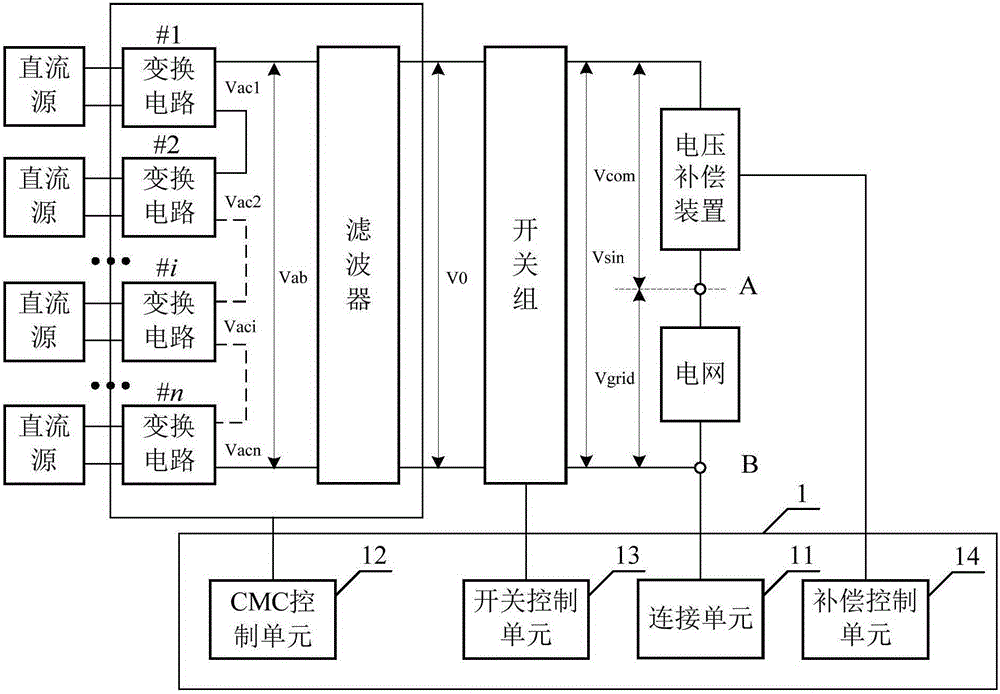
[0060] Please refer to image 3 , image 3 A structural schematic diagram of a control device for an inverter system provided by the present invention; the control device 1 is applied to an inverter system, and the inverter system includes a switch group and a cascaded multi-level converter CMC connected through the switch group and a voltage compensation Device, control device 1 comprises:

[0061] A connection unit 11, configured to connect the output end of the inverter system to the grid;

[0062] The CMC control unit 12 is used to start the conversion circuit in the CMC and control the CMC to output the sinusoidal AC voltage V 0 ;

[0063] Understandably, image 3 The DC source can be PV (photovoltaic, photovoltaic) panels, batteries, supercapacitors, fuel cells and other units that can emit or store energy, or it can be a DC source formed by adding a corresponding matching circuit to the above units.

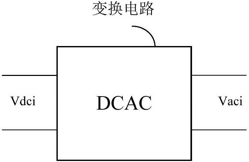
[0064] In addition, the changing circuit here can be a DCAC modu...

Embodiment 2

[0098] Please refer to Figure 15 , Figure 15 A schematic structural diagram of an inverter system provided by the present invention;

[0099] The inverter system includes a switch group 3 , a cascaded multilevel converter CMC2 and a voltage compensation device 4 connected through the switch group 3 , and also includes the above-mentioned control device 1 .

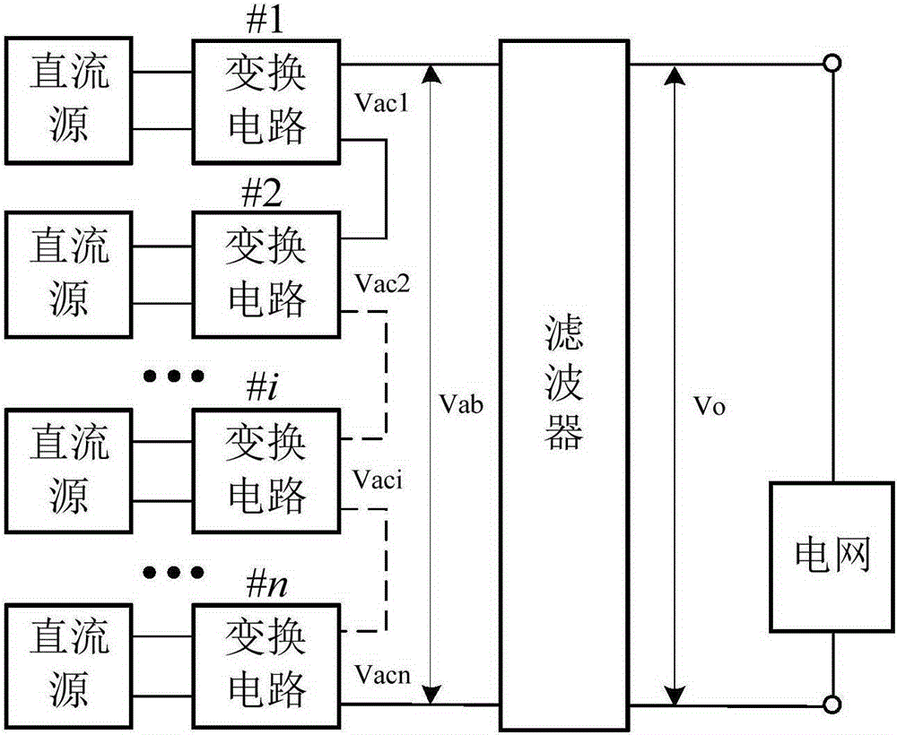
[0100] Preferably, the CMC2 includes a plurality of series-connected DCAC modules and a filter connected to the output terminals of the plurality of series-connected DCAC modules.

[0101] Specifically, please refer to Figure 16 , Figure 16 A schematic circuit diagram of a switch group provided by the present invention;

[0102] The switch group 3 is a two-stage switch group, including switch K R1 , switch K R2 , switch K R3 and switch K R4 , where the switch K R1 and switch K R2 in series, switch K R3 and switch K R4 In series, the connection of the four switches here meets the safety requirements of the p...

Embodiment 3

[0106] Please refer to Figure 17 , Figure 17 It is a flow chart of the process of a control method of an inverter system provided by the present invention, the control method is applied to an inverter system, and the inverter system includes a switch group and cascaded multi-level conversion connected through the switch group tor CMC and voltage compensation device, including:

[0107] Step s101: connecting the output end of the inverter system to the grid;

[0108] Step s102: start the conversion circuit in the CMC, and control the CMC to output the sinusoidal AC voltage V 0 ;

[0109] Step s103: when V 0 The effective value of the preset sinusoidal AC voltage V sin When the difference of the RMS value is within the preset range, the control switch group is closed, and the CMC is connected to the power grid through the voltage compensation device;

[0110] Step s104: start the voltage compensation device, and adjust the output voltage V of the voltage compensation dev...


PUM


Abstract

The invention discloses a control device of an inverter system, which is applied to the inverter system. The inverter system comprises a switching group, and a CMC and a voltage compensation device which are connected through the switching group, wherein the control device comprises a connection unit, a CMC control unit, a switching control unit and a compensation control unit; the connection unit is used for connecting the output end of the inverter system to a power grid; the CMC control unit is used for starting up a conversion circuit in the CMC and controlling the CMC to output sine alternating voltage V0; the switching control unit is used for controlling the switching group to be switched off when a difference value between an effective value of the V0 and an effective value of pre-set sine alternating voltage Vsin is in a pre-set range, and the CMC is connected into the power grid through the voltage compensation device; and the compensation control unit is used for starting up the voltage compensation device and adjusting output voltage Vcom of the voltage compensation device so that the sum of the Vcom and voltage Vgrid of the power grid is equal to the Vsin. Visibly, the voltage compensation device can be used for compensating distorted voltage of the power grid and the influences on the CMC by the distortion of the power grid are eliminated, so that the inverter system has a relatively good output waveform and a relatively rapid responding speed. The invention further discloses the inverter system and a control method thereof.

Description

technical field [0001] The invention relates to the technical field of inverter system control, in particular to an inverter system and its control device and method. Background technique [0002] Cascaded multilevel converters (CascadedMultilevelConverters, CMC) can be applied to a variety of workplaces, among which photovoltaic power generation systems are a common application, please refer to figure 1 and figure 2 ,in, figure 1 It is a schematic diagram of the principle of an inverter system integrated into the power grid provided by the present invention, figure 2 A conversion circuit provided by the present invention is a structural schematic diagram of a DCAC module. The cascaded multilevel converter CMC includes n sequentially connected DCAC modules and one general filter. [0003] When the cascaded multilevel converter topology is used in a photovoltaic power generation system, in order to ensure the overall cost and efficiency of the photovoltaic power generati...

Claims


Application Information

Patent Timeline
Patent Type & Authority Applications(China)
IPC IPC(8): H02J3/38H02M7/49
Inventor 刘宝其肖永利曾志槐
Owner SUNGROW POWER SUPPLY CO LTD
Why Eureka
Try Eureka