Supercharge Your Innovation With Domain-Expert AI Agents!

Motor Driving Device

A driving device and motor technology, applied in motor control, motor generator control, electric/electric converter, etc., can solve problems such as motor drive device or motor damage

Inactive Publication Date: 2015-12-23
ROHM CO LTD
View PDF6 Cites 2 Cited by
  • Summary
  • Abstract
  • Description
  • Claims
  • Application Information

AI Technical Summary

Problems solved by technology

[0002] When the motor is started or driven, if the motor is in a restrained state (or an abnormal state similar to it) due to some factors (the motor is pressed by hand, etc.), a current continues to flow into a specific phase (from the U phase) to V equal) resulting in the danger of damage to the motor drive or the motor

Method used


Image

  • Motor Driving Device
  • Motor Driving Device
  • Motor Driving Device

Examples


Embodiment Construction

[0031]

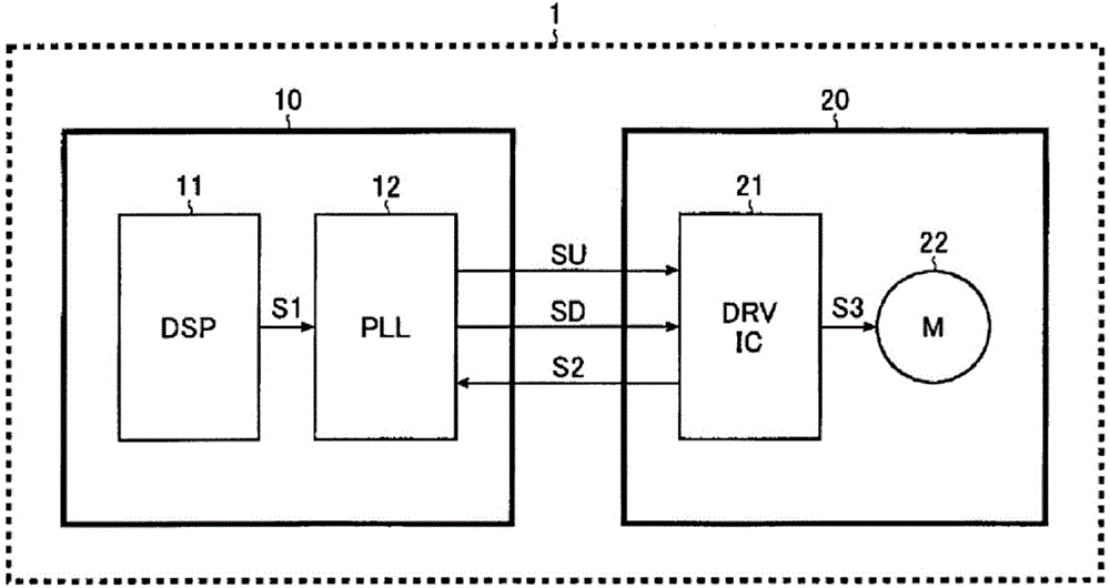
[0032] figure 1 It is a block diagram showing the overall configuration of the electronic device. The electronic device 1 of this configuration example includes a main board 10 and a motor board 20 . A digital signal processor 11 (hereinafter referred to as DSP [digital signal processor] 11 ) and a PLL circuit 12 are mounted on the main substrate 10 . On the other hand, a motor driver IC 21 and a sensorless motor 22 are mounted on the motor board 20 .

[0033] The DSP 11 generates a target rotational speed signal S1 (frequency signal) corresponding to the target rotational speed of the sensorless motor 22 and outputs it to the PLL circuit 12 .

[0034] The PLL circuit 12 performs phase synchronization control on the target rotational speed signal S1 input from the DSP11 and the motor rotational speed signal S2 (called a frequency signal of a FG (Frequency Generator, frequency generator) signal) input from the motor driver IC21 to generate the acceleration signal S...


PUM


Abstract

The present invention provides a motor driving device for easily and accurately detecting an abnormal status of a motor. The motor driving device (21) includes a control circuit (100) for generating a driver control signal (S10); a driving circuit (200) for generating a motor driving signal (S3) according to the driver control signal (S10); an initial position detecting circuit (300) for detecting an initial position of a motor (22); and a rotation detecting circuit (400) for detecting a rotation status of the motor (22). Before the motor (22) starts to rotate normally, the control circuit (100) repeatedly performs a serial activation processing including detecting an initial position; applying an initial torque and detecting a motor rotation, and when the repetition number reaches a threshold value 'm' (for example, m=5), the motor (22) is forced stop.

Description

technical field [0001] The invention relates to a motor drive device. Background technique [0002] When the motor is started or driven, if the motor is in a restrained state (or an abnormal state similar to it) due to some factors (the motor is pressed by hand, etc.), a current continues to flow into a specific phase (from the U phase) to V equal) resulting in the danger of damage to the motor drive or the motor. [0003] Therefore, in the existing motor drive device, a restraint protection circuit is mounted. When the pulse of the FG (Frequency Generator, frequency generator) signal (motor speed signal) is not generated for a predetermined time, the restraint protection circuit will determine that the motor is restrained. state and forcibly stops the drive of the motor. [0004] Moreover, patent document 1 is mentioned as an example of the prior art related to this invention. [0005] [Prior Art Literature] [0006] [Patent Document] [0007] [Patent Document 1] Japan...

Claims


Application Information

Patent Timeline
Patent Type & Authority Applications(China)
IPC IPC(8): H02P6/08
CPCH02P1/022H02P1/029H02H7/0851H02P29/0241G05B23/00
Inventor 国田祐司吉谷崇志
Owner ROHM CO LTD
Features
  • R&D
  • Intellectual Property
  • Life Sciences
  • Materials
  • Tech Scout
  • Unparalleled Data Quality
  • Higher Quality Content
  • 60% Fewer Hallucinations
Learn More