Inertial velocity sensor signal processing circuit and inertial velocity sensor device provided with the same
A signal processing circuit, speed sensor technology, applied in the direction of speed/acceleration/shock measurement, measurement device, gyro effect for speed measurement, etc., can solve problems such as failure to perform fault detection
- Summary
- Abstract
- Description
- Claims
- Application Information
AI Technical Summary
Problems solved by technology
Method used
Image

Examples
Embodiment approach 1
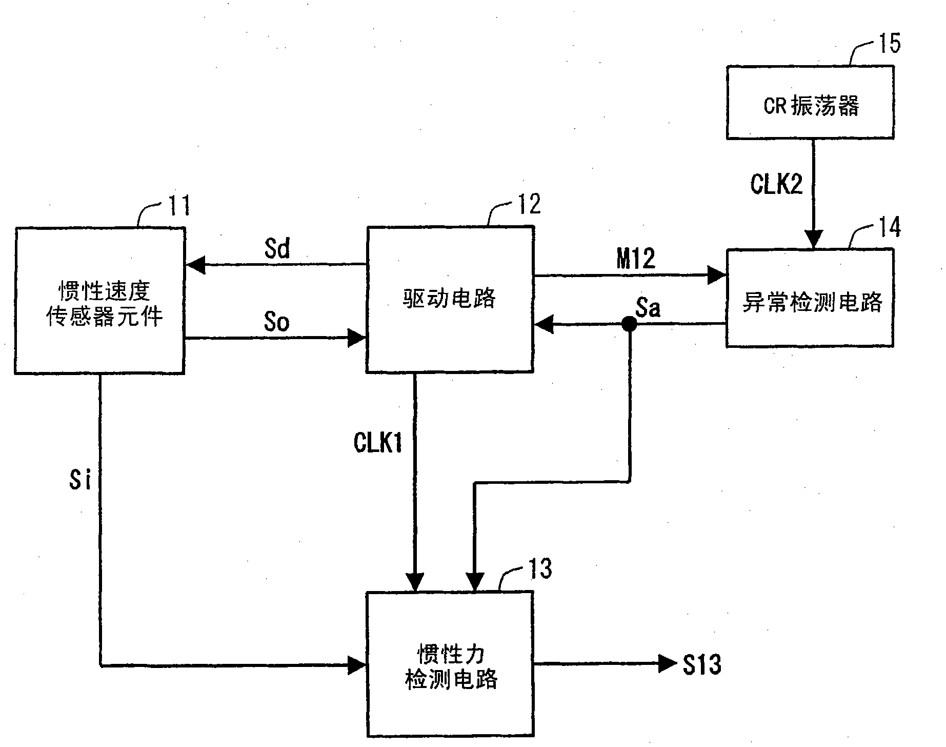
[0055] figure 1 It shows the structure of the inertial velocity sensor device which concerns on Embodiment 1 of this invention. The inertial speed sensor device includes an inertial speed sensor element 11 , a drive circuit 12 , an inertial force detection circuit 13 , an abnormality detection circuit 14 , and a CR oscillator 15 .
[0056] 〔Inertial speed sensor〕
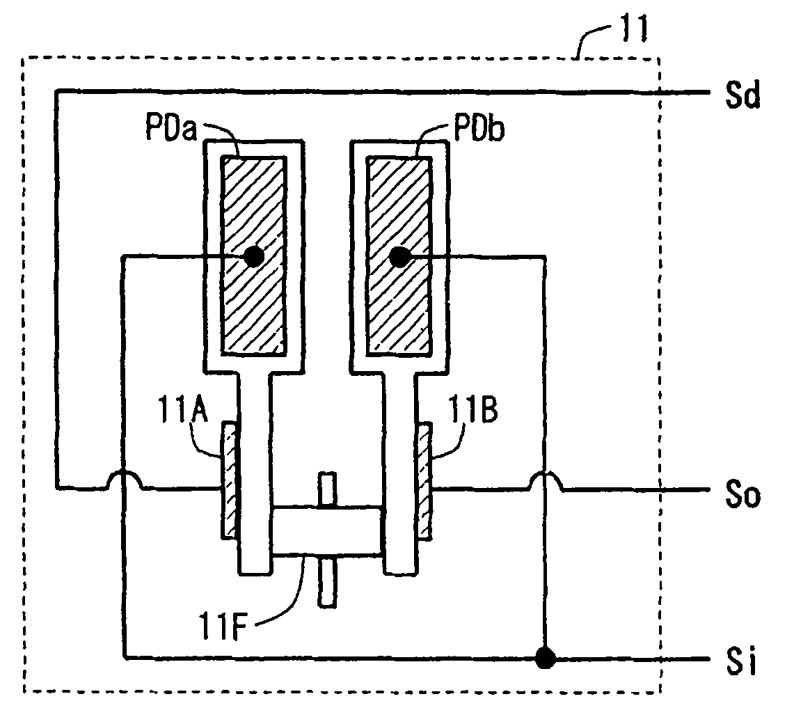
[0057] The inertial speed sensor element 11 vibrates according to the frequency and amplitude of the drive signal Sd from the drive circuit 12, outputs a vibration signal So corresponding to the vibration, and outputs a force corresponding to the inertial force (for example, Coriolis force) applied to itself. ) corresponds to the sensor signal Si . For example figure 2 As shown, the inertial velocity sensor element 11 has a tuning fork main body 11F, a driving piezoelectric element 11A, a vibration detecting piezoelectric element 11B, and angular velocity detecting piezoelectric elements PDa, PDb. The tuning fo...
Embodiment approach 2
[0072] Figure 6 The configuration of the inertial velocity sensor device according to Embodiment 2 of the present invention is shown. The inertial speed sensor device replaces the figure 1 The shown inertial force detection circuit 13 has an inertial force detection circuit 23 and also has a PLL circuit 21 that multiplies a clock signal CLK1 from the drive circuit 12 to generate an operating clock CLK3 . other structures with figure 1 same.
[0073] 〔Inertial force detection circuit〕
[0074] Figure 7 express Figure 6 The internal structure of the inertial force detection circuit 23 is shown. After the inertial force detection circuit 23 converts the sensor signal Si from the inertial speed sensor element 11 into a digital sensor signal, it extracts from the digital sensor signal using a digital detection signal (a detection signal generated based on the operation clock CLK3 from the PLL circuit 21). Inertial force component (digital signal corresponding to the inert...
Embodiment approach 3
[0080] Figure 9 The configuration of the inertial velocity sensor device according to Embodiment 3 of the present invention is shown. The inertial velocity sensor device is in addition to Figure 6 In addition to the structure shown, it also has a temperature monitoring circuit 31 , an EEPROM (Electrically Erasable Programmable Read-Only Memory) 32 , and a control circuit 33 . In addition, the abnormality detection circuit 14 detects the abnormality of the PLL circuit 21, the inertial force detection circuit 23, the temperature monitoring circuit 31, and the EEPROM 32 in addition to detecting the abnormality of the drive circuit 12. Here, the drive circuit 12 , abnormality detection circuit 14 , PLL circuit 21 , inertial force detection circuit 23 , temperature monitoring circuit 31 , and control circuit 33 are incorporated in the same semiconductor integrated circuit (or the same package).
[0081] 〔Abnormity detection circuit〕
[0082] In addition to receiving the monito...
PUM
 Abstract
Description
Claims
Application Information