
Dermatoscope

A dermatoscope and rotating disk technology, applied in the field of dermatoscope, can solve the problems of complicated circuit switch control structure, many polarizers, inconvenient installation, use and maintenance, etc., and achieves the effects of compact structure, stable performance and convenient maintenance.

Inactive Publication Date: 2015-12-30
ZUMAX MEDICAL
View PDF12 Cites 3 Cited by
  • Summary
  • Abstract
  • Description
  • Claims
  • Application Information

AI Technical Summary

Problems solved by technology

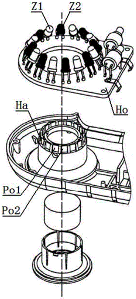
like figure 1 As shown: the illumination source of this invention is through a ring seat Ho concentric with the optical axis of the observation objective lens, and there are 16 evenly distributed LED tubes on the ring seat Ho, which are divided into two groups of illumination sources Z1 and Z2, and are arranged alternately at intervals. Parallel and crossed polarizers Po1 and Po2 are arranged in the polarizing ring Ha corresponding to the opening optical path of the odd and even LED tubes, and the illumination light converges at a certain angle on the focusing area on the optical axis of the observation objective lens through the polarizer, and the illumination source Z1 , The LED of Z2 is converted into polarized light or white light by switch control, and at the same time, the skin under inspection is imaged into the human eye Y through the objective lens.

Method used


Image

  • Dermatoscope
  • Dermatoscope
  • Dermatoscope

Examples


Embodiment approach

[0030] method one:

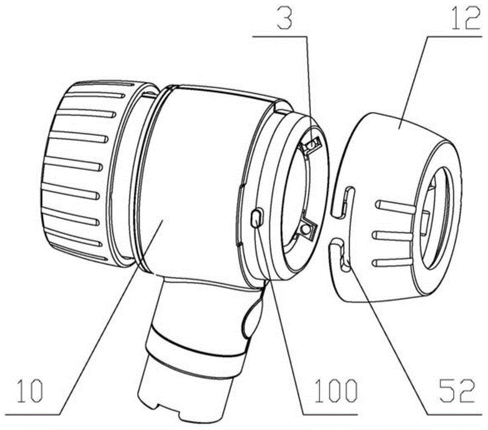
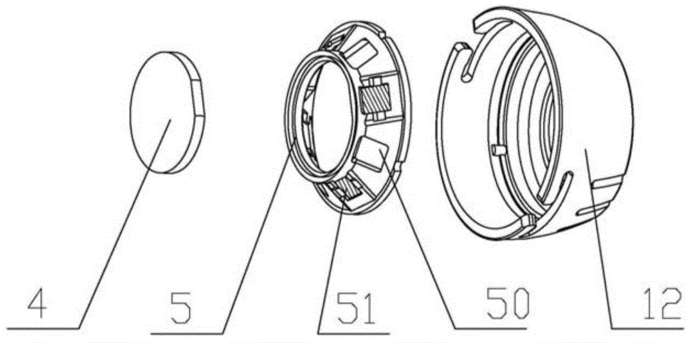
[0031] The window 50 of the rotary disk 5 is provided with an illumination polarizer 51, and the illuminating light of the illuminant passes through the illumination polarizer 51 to illuminate the working surface of the dermatoscope. Windows 50 on.

[0032] further programs such as image 3 As shown, the illumination polarizers 51 are distributed on a plurality of windows 50 of the rotating disk 5 at intervals. When the rotating disk 5 is rotated and switched, the illumination light path can be switched with / without the illumination polarizer 51 .

[0033] Method 2:

[0034] The front portion of the illuminant is provided with an illuminating polarizer 51, and the illuminating light of the illuminant passes through the illuminating polarizer 51 and the window 50 to illuminate the working surface of the dermatoscope. or all illuminant fronts.

[0035] Ways 1 and 2 need to be used in conjunction with the viewing polarizer 4 . That is, the re...


PUM


Abstract

The invention relates to a dermatoscope which comprises an observation system and an illumination system. The illumination system comprises at least one luminous body and a rotary plate capable of rotating around the optical axis of the observation system. The rotary plate is provided with multiple windows. When the rotary plate rotates and is switched in place, luminous light of at least one luminous body illuminates the work face of the dermatoscope through at least one window. The dermatoscope is compact in structure, multifunctional, stable in performance and convenient to assemble, adjust, use and maintain.

Description

Technical field [0001] The present invention involves a derm mirror. Background technique [0002] The skin is the largest organs of the body. We usually use skin mirrors to perform external optical imaging of this organ, check the health of the skin tissue, diagnose tumor lesions, and clearly observe the deep and subtle structure of the skin pigment damage site after polarizing tablets. [0003] See the US patent with US7006223B2, and it publicly discloses a "device using cross -peaceful dermatology (dermoscopyepilumineSceeEMPLOSSALLELARization)".like figure 1 Show: The lighting source of the invention is a ring ho with a ring with an observation mirror light shaft. There are 16 evenly distributed LED tubes on the ring ho, which are divided into two sets of lighting sources Z1 and Z2, and the interval is alternately arranged.There are parallel and cross -polarizers PO1 and PO2 corresponding to the polarized ring HA of the opening light path of the LED tube of the LED tube., Z2's...

Claims


Application Information

Patent Timeline
Patent Type & Authority Applications(China)
IPC IPC(8): A61B5/00
Inventor 沈顺国李剑月杨晓华陈小甜
Owner ZUMAX MEDICAL
Learn More