
Medical detection device

A detection device and medical technology, applied in the field of medical devices, can solve the problems of inability to treat patients in a timely manner, cost a lot, and cannot be realized, and achieve a situation that is beneficial to clinical guidance and nursing, avoids multiple trips to and from the hospital, and saves operation coordination time. Effect

Inactive Publication Date: 2015-12-30
滕大志
View PDF7 Cites 17 Cited by
  • Summary
  • Abstract
  • Description
  • Claims
  • Application Information

AI Technical Summary

Problems solved by technology

The existing problems are: on the one hand, it often takes more time to identify the actual cause of disease after the patient has symptoms. If the patient does suffer from heart disease, it will bring huge harm to the patient if he cannot be treated in time or missed diagnosis.
However, the current hospital medical equipment usually detects the patient's ECG in the ward, and the detection of cardiac markers needs to be performed in the laboratory. Therefore, there is no medical device that can detect the patient's ECG and cardiac markers at the same time testing, that is, actual use that does not meet the above guidelines
Furthermore, the transformation of chronic heart disease into acute coronary syndrome is an uncertain process. Once an attack occurs, the probability of sudden life-threatening is extremely high
With the existing medical diagnostic equipment, it is still impossible to construct ECG and cardiac markers on the same device, and it is impossible to realize the periodic application of cardiac function in chronic heart disease patients on one device through clinical nurses. Detection to achieve the purpose of periodically discovering changes in cardiac function and assisting clinical treatment detection

Method used


Image

  • Medical detection device
  • Medical detection device
  • Medical detection device

Examples


Embodiment Construction

[0028] In order to make the object, technical solution and advantages of the present invention clearer, the present invention will be described in further detail below in conjunction with specific embodiments and with reference to the accompanying drawings.

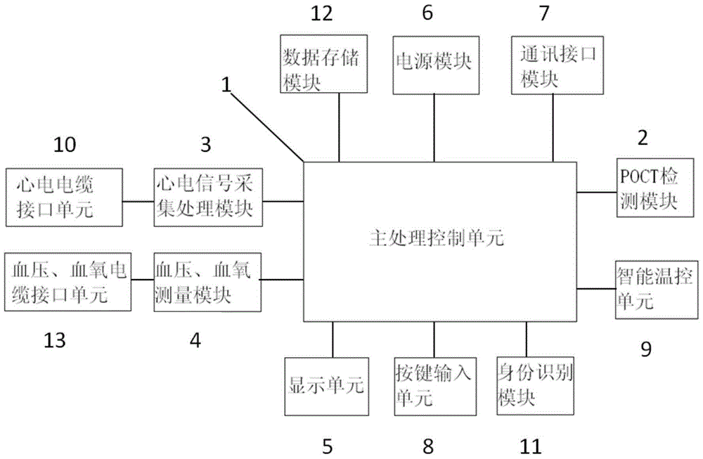
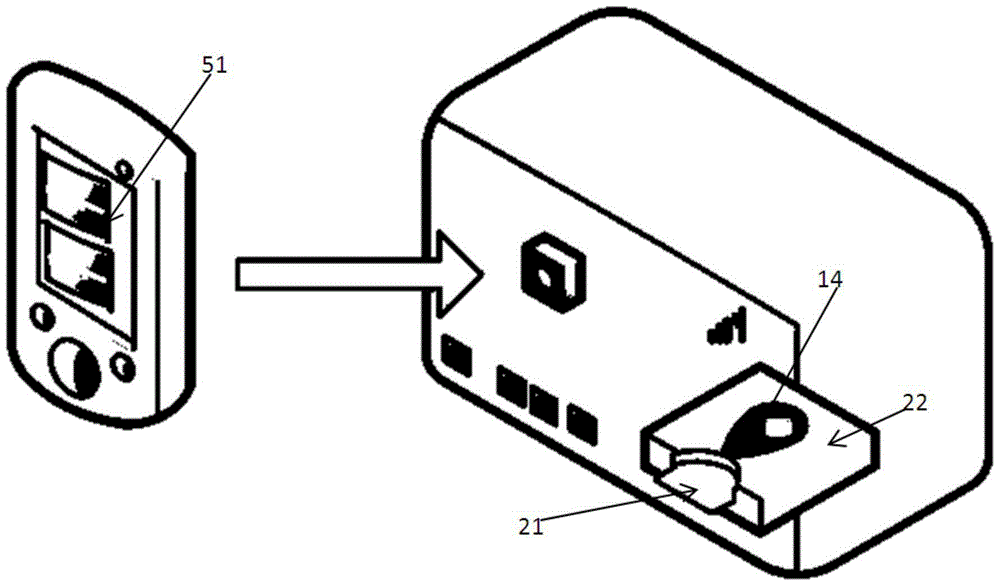
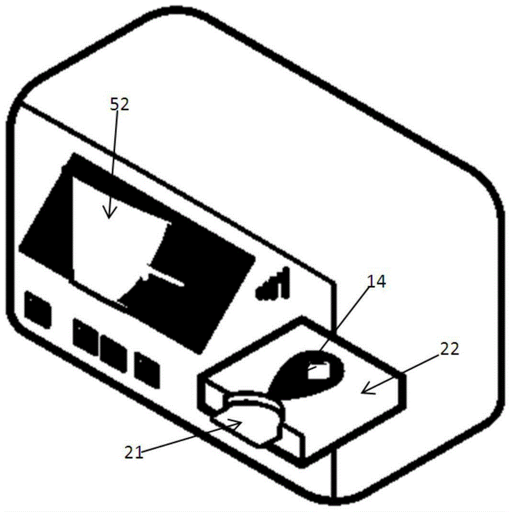
[0029] refer to figure 1 Shown is a structural block diagram of a medical detection device according to an embodiment of the present invention. The medical detection device includes: a main processing control unit 1, a data storage module 12, a POCT detection module 2, an electrocardiographic signal acquisition and processing module 3, a display unit 5, a power supply module 6, a communication interface module 7 and a key input unit 8; The data storage module 12, the POCT detection module 2, the ECG signal acquisition and processing module 3, the display unit 5, the power supply module 6, the communication interface module 7 and the key input unit 8 are respectively connected with The main processing control unit 1 is co...


PUM


Abstract

The invention discloses a medical detection device which comprises a main processing control unit, a data storage module, a POCT module, an electrocardiosignal collecting and processing module, a display unit, a power module, a communication interface module and a key input unit. The data storage module, the POCT module, the electrocardiosignal collecting and processing module, the display unit, the power module, the communication interface module and the key input unit are respectively connected with the main processing control unit. By means of the medical detection device, an electrocardiogram and cardiac marker content of a patient can be rapidly obtained and can be displayed at the same time, medical staff can conveniently make a judgment in time, and time spent for operating two kinds of equipment is shortened; when the patient is away from a hospital, nursing personnel with the medical qualification at home or a community health care center can examine the patient and share examination data of the patient with a doctor remotely, the patient avoids going to and from the hospital repeatedly, meanwhile, the doctor can master the illness state of the patient at any time, and illness state prediction and specific treatment are carried out in time.

Description

technical field [0001] The invention relates to the technical field of medical devices, in particular to a medical detection device. Background technique [0002] For people suffering from cardiovascular diseases, especially high-risk groups such as heart disease, if they cannot be treated in time, they will often endanger their lives. And the problem that exists at present is: on the one hand, often need to spend more time to identify the actual cause of disease after the patient shows symptoms, if the patient really suffers from heart disease, can't treat in time or missed diagnosis will bring huge harm to the patient. For example, in myocardial infarction, reversible ischemia occurs first in myocardial tissue, followed by irreversible ischemia, and finally necrosis of myocardial tissue occurs. If the patient can be treated before irreversible ischemia occurs, it is very likely that the patient will recover completely. On the other hand, for symptoms not caused by heart d...

Claims


Application Information

Patent Timeline
IPC IPC(8): A61B5/0402A61B5/00A61B5/117
Inventor 滕大志王瑾
Owner 滕大志
Learn More