

Rectification device
A rectification and rectification column technology, which is applied in the field of rectification equipment, can solve the problem of high energy consumption of rectification equipment, and achieve the effects of saving power consumption, significant mass and heat transfer effects, and small movement
- Summary
- Abstract
- Description
- Claims
- Application Information
AI Technical Summary
Problems solved by technology
Method used
Image

Examples
Embodiment 1
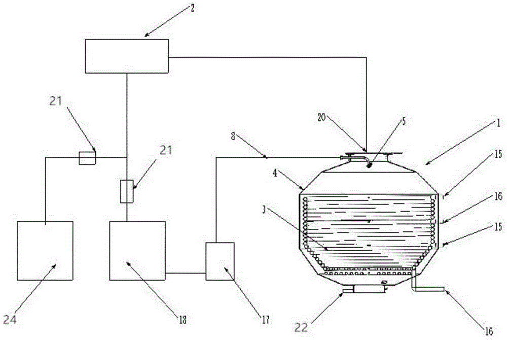
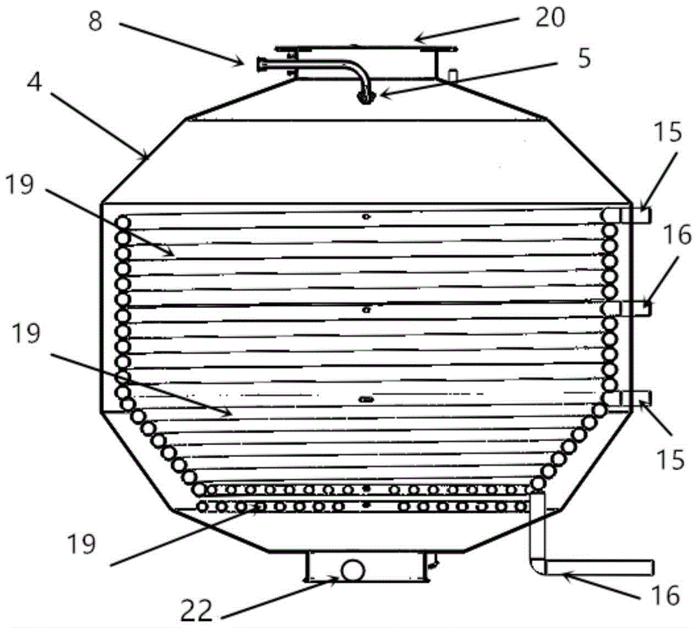
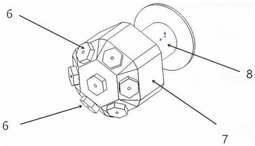
[0041] refer to figure 1 , figure 2 , image 3 , In one embodiment, the rectification device of the present invention includes: an evaporation chamber 1 and a condenser 2; wherein, the upper part of the evaporation chamber 1 communicates with the condenser 2; the evaporation chamber 1 further includes: a heating device 3, a shell body 4, an atomizer 5, the atomizer 5 further includes a nozzle 6, a nozzle seat 7; the upper part of the housing 4 has a volatile phase outlet 20, and the condenser 2 receives the volatile phase through a pipeline The gas phase with high volatile phase content emitted by the phase outlet 20; an atomizer 5 is installed in the evaporation chamber 1, and the nozzle 6 in the atomizer 5 is installed on the nozzle seat 7, and the nozzle seat 7 communicates with the feed pipe 8; a heating device 3 is installed on the inner side wall and bottom of the housing 4, and the heating device 3 realizes heat exchange with the outside world through a heat medium i...
Embodiment 2
[0045] In another embodiment, on the basis of the previous embodiment, the rectification device of the present invention further includes a rectification column 9 and a reboiler 23 . Specifically, in this example, refer to Figure 4 , Figure 5 and Figure 7, the rectification device of the present invention comprises an evaporation chamber 1, a condenser 2, a rectification column 9, and a reboiler 23; wherein, the top of the evaporation chamber 1 communicates with the rectification column 9, and the top of the rectification column 9 It communicates with the condenser 2; the evaporation chamber 1 further includes: a heating device 3, a housing 4, and an atomizer 5, and the atomizer 5 further includes a nozzle 6 and a nozzle seat 7; the housing 4 is an upper, A sealed container with a lower opening, the upper opening of which communicates with the rectification column 9, the upper part of the rectification column 9 has a volatile phase outlet 20, and the condenser 2 receives ...
Embodiment 3
[0048] In another embodiment, on the basis of the first embodiment, the rectification device of the present invention further includes a rectification evaporation chamber 14 and a reboiler 23 . Specifically, if Figure 6 As shown, the rectification device of the present invention includes an evaporation chamber 1, a condenser 2, a rectification evaporation chamber 14, and a reboiler 23; wherein, the bottom of the evaporation chamber 1 communicates with the reboiler 23, and its top communicates with the rectification chamber 1. The evaporation chamber 14 communicates, and the top of the rectification evaporation chamber 14 communicates with the condenser 2; the evaporation chamber 1 and the rectification evaporation chamber 14 have the same structure, and each includes: a heating device 3, a housing 4, an atomizing device 5, the atomizer 5 further includes a nozzle 6, a nozzle seat 7; The opening of the lower part of the housing 4 is connected, and the upper part of the housin...
PUM
 Abstract
Description
Claims
Application Information