
Circulating stirring device

A technology of circulating stirring and stirring device, applied in the field of liquid stirring machinery, can solve the problems of uneven concentration difference between upper and lower layers, and achieve the effect of narrowing the width range

Inactive Publication Date: 2015-12-30
西达(无锡)生物科技有限公司
View PDF5 Cites 6 Cited by
  • Summary
  • Abstract
  • Description
  • Claims
  • Application Information

AI Technical Summary

Problems solved by technology

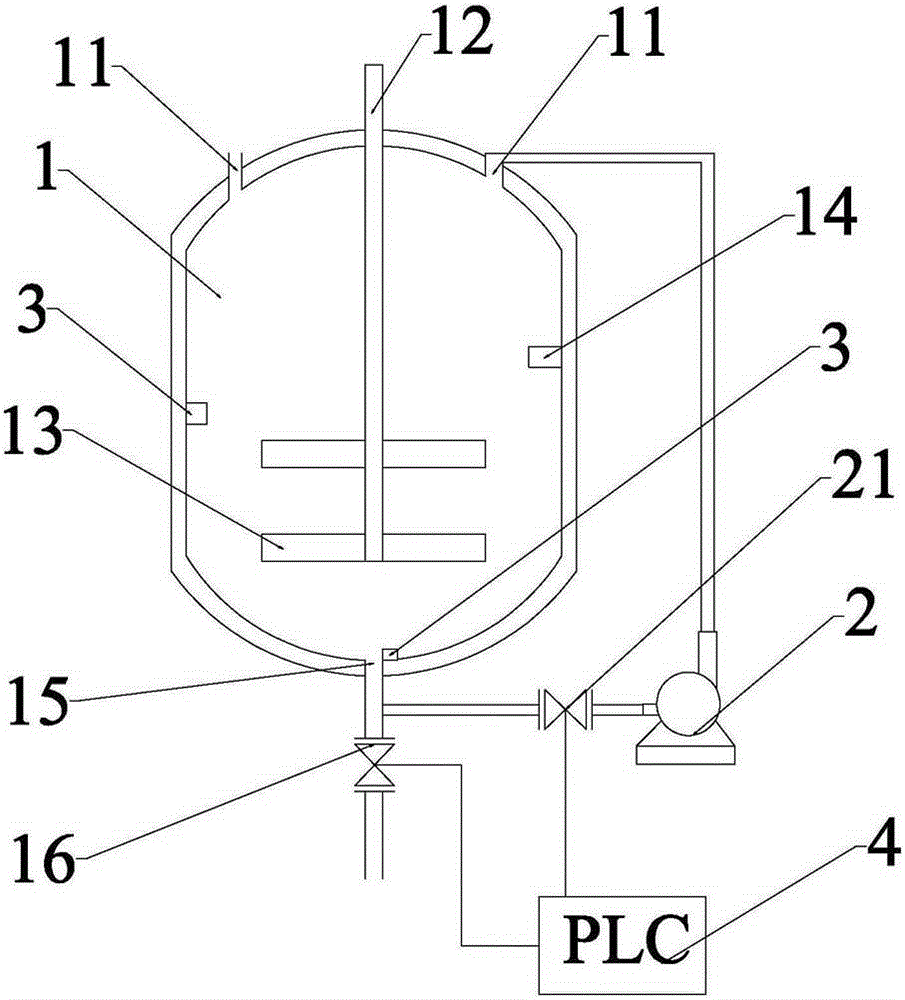
[0003] Aiming at the problem of large concentration difference between the upper and lower layers of liquid molecules in the reactor in the prior art, the present invention provides a circulating stirring device to solve the problem of uneven concentration difference between the upper and lower layers. In order to achieve the above purpose, the present invention adopts the following technical solutions: the present invention It includes a reactor 1, a circulating pump 2, a sensor 3, and a PLC controller 4. The top of the reactor 1 is provided with a feed port 11 and a power drive shaft 12. The internal cavity of the reactor 1 is provided with a drive shaft connected to the power 12 connected stirring device 13, liquid level gauge 14, at least two concentration sensors 3, the bottom of the reaction kettle 1 is provided with a discharge port 15;

Method used


Image

  • Circulating stirring device

Examples


Embodiment Construction

[0014] Have figure 1 It can be seen that the present invention includes a reactor 1, a circulating pump 2, a sensor 3, and a PLC controller 4. The top of the reactor 1 is provided with a feed port 11 and a power drive shaft 12. In the inner cavity of the reactor 1, A stirring device 13 connected to the power drive shaft 12, a liquid level gauge 14, and at least two concentration sensors 3 are provided, and a discharge port 15 is provided at the bottom of the reaction kettle 1;

[0015] One end of the circulating pump 2 is connected to the discharge port 15, and the other end of the circulating pump 2 is connected to the feed port 11 of the reactor 1;

[0016] The PLC controller 4 is connected with the liquid level gauge 14 , the circulating pump 2 , the sensor 3 and the stirring device 13 .

[0017] Preferably, the discharge port 15 is provided with a discharge valve 16 , and the discharge valve 16 is connected to the PLC controller 4 .

[0018] Preferably, a circulation val...


PUM


Abstract

The invention provides a circulating stirring device which comprises a reaction kettle, a circulating pump, a sensor and a PLC (Programmable Logic Controller), wherein a feed port and a power driving shaft are arranged on the top of the reaction kettle, a stirring device, a liquid level meter and at least two concentration sensors which are connected with the power driving shaft are arranged in a cavity in the reaction kettle, and a discharge port is formed in the bottom of the reaction kettle; one end of the circulating pump is connected with the discharge port, and the other end of the circulating pump is connected with the feed port of the reaction kettle; the PLC is connected with the liquid level meter, the circulating pump, the sensor and the stirring device. According to the circulating stirring device, the circulating pump is connected between the feed port and the discharge port of the reaction kettle, the circulating pump is controlled to operate according to the concentration or density value measured by the control end of the PLC and the concentration sensors in the reaction kettle, so that materials at the bottom of the reaction kettle are returned to the top of the reaction kettle, a quick up-and-down stirring passage is created for the reaction kettle, and the concentration difference between upper and lower layers of materials is greatly reduced and can be completely ignored, so that the width range of a molecular weight is synchronously narrowed.

Description

technical field [0001] The invention relates to the field of liquid stirring machinery, in particular to a circulating stirring device. Background technique [0002] The dropwise polymerization reaction of liquid polymers has a different viscosity between the upper and lower layers of the reactor when the viscosity is high. Although there is stirring, there is still a concentration difference between the upper and lower layers, which is reflected in the different molecular weights of the materials. That is to say, the wide range of molecular weight is large, which is not conducive to the selection and use of customers. Contents of the invention [0003] Aiming at the problem of large concentration difference between the upper and lower layers of liquid molecules in the reactor in the prior art, the present invention provides a circulating stirring device to solve the problem of uneven concentration difference between the upper and lower layers. In order to achieve the abov...

Claims


Application Information

Patent Timeline
Patent Type & Authority Applications(China)
IPC IPC(8): B01J19/18
Inventor 尹国成
Owner 西达(无锡)生物科技有限公司
Learn More