Separating method and device for organic matter-inorganic salt in high-salt high-COD wastewater

A separation method and technology of separation device, which are applied in separation methods, dispersed particle separation, chemical instruments and methods, etc., can solve the problems of unsuitable treatment of small flow wastewater, large demand for circulating water, increased economic costs and equipment occupation.

Pending Publication Date: 2018-10-23
浙江迪萧科技有限公司
View PDF5 Cites 2 Cited by
  • Summary
  • Abstract
  • Description
  • Claims
  • Application Information

AI Technical Summary

Problems solved by technology

However, increasing the number of stages of an electrically driven membrane device requires a corresponding increase in mult

Method used


Image

  • Separating method and device for organic matter-inorganic salt in high-salt high-COD wastewater
  • Separating method and device for organic matter-inorganic salt in high-salt high-COD wastewater
  • Separating method and device for organic matter-inorganic salt in high-salt high-COD wastewater

Examples


Embodiment 1

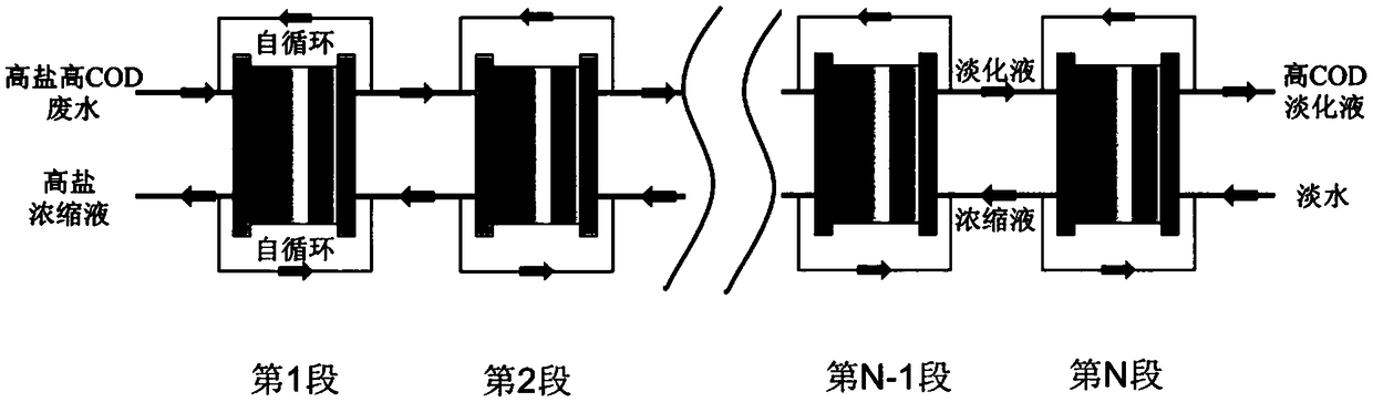
[0029] refer to figure 1 , a separation device for organic matter-inorganic salts in high-salt and high-COD wastewater, including: at least one section of special electric-driven membrane device, the entrance of the desalination chamber and the entrance of the concentration chamber of the special electric-driven membrane device are respectively arranged in the special electric-driven membrane device The flow direction of high-salt and high-COD wastewater is opposite to the flow direction of fresh water, and two adjacent sections of special electric-driven membrane devices are connected in series.

[0030] A self-circulation pipeline connecting the outlet of the desalination chamber and the inlet of the desalination chamber is arranged between the outlet of the desalination chamber and the inlet of the desalination chamber of each section of the special electric-driven membrane device.

[0031] A self-circulation pipeline connecting the outlet of the concentration chamber and t...

Embodiment 2

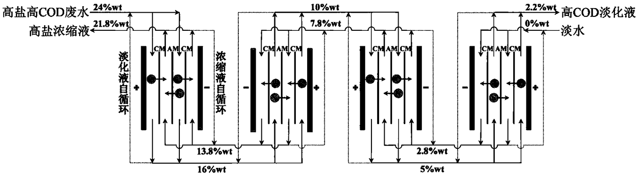
[0037] The raw material is amine waste water with a salt content of 24%wt, a pH of 13.4, and a COD of 15.2 g / L. image 3 As shown, the current density is 280 A / m 2 , the operating power is 21 Kw, and the cycle runs for 10 minutes to obtain a desalinated solution with a salt content of 16%wt and a COD of 13.4 g / L. m 2 , the operating power is 12 Kw, and the cycle runs for 10 minutes to obtain a desalinated solution with a salt content of 10% wt and a COD of 12.2 g / L. m 2 , the operating power is 10 Kw, and the cycle runs for 10 minutes to obtain a desalinated solution with a salt content of 5%wt and a COD of 11.2 g / L. m 2 , operating power 8 Kw, cycled for 10 minutes to obtain a desalinated solution with a salt content of 2.2%wt and a COD of 10.4 g / L, and passed the fresh water into the concentration chamber of the fourth special electric-driven membrane device with a current density of 100A / m 2 , operating power 8 Kw, cycled for 10 minutes to obtain a concentrated solut...


PUM


Abstract

The invention provides a separating method and device for organic matter-inorganic salt in high-salt high-COD wastewater. A multi-section special electric driving film device is used; through cross flow feeding of a desalting chamber and a concentrating chamber, a concentration difference of each section of the special electric driving film device is reduced, and the efficient separation of organic matters and inorganic salt is realized; desalting liquid and concentrating liquid of each section of the special electric driving film device are directly refluxed to realize film stack self-circulation, the usage amounts of a multi-way valve and a water tank are reduced, and water inlet flows of the desalting chamber and the concentrating chamber of each section of special electric driving filmdevice are controlled to be consistent through the valve, so the demanded quantity of circulating water of a system and the film stack stability are greatly reduced. In addition, the device is capable of performing crystallization processing on the concentrating liquid obtained by the first section of special electric driving film device, acquiring the high-purity inorganic salt, and performing follow-up deep processing on the desalting liquid obtained by the last section of special electric driving film device; the up-to-standard discharge is realized, and the device has better social and economic benefits.

Description

technical field [0001] The invention belongs to the field of industrial sewage treatment, and relates to a method and a device for separating organic matter and inorganic salt in high-salt and high-COD waste water. Background technique [0002] A considerable part of the wastewater discharged from industries such as medicine, food, electroplating, and chemical industry carries organic raw materials, intermediates, and reaction by-products, and the pollutants have complex components and high concentrations. Because this type of wastewater not only has a high concentration of COD, but also contains a high concentration of salt, it is difficult to achieve effective treatment by traditional biological methods; for the widely used evaporation desalination technology in industry, the high concentration of organic matter in wastewater will not only cause damage to the evaporation system, but also cause damage to the evaporation system. Cause the organic matter content in the crysta...

Claims


Application Information

Patent Timeline
IPC IPC(8): C02F1/469
CPCC02F1/469C02F2301/08
Inventor 不公告发明人
Owner 浙江迪萧科技有限公司
Why Eureka
Try Eureka