Treatment system and method for separating uranyl ions in concentrated nitric acid system by adopting membrane technology

A technology of uranyl ion and treatment system, which is applied to the field of treatment system of uranyl ion under membrane technology separation and concentrated nitric acid system, can solve the problems of increasing operating pressure, inability to operate, and difficulty in reaching concentrated materials, and achieves improved removal efficiency and reduced The effect of operating pressure

Pending Publication Date: 2019-01-25
北京清核朝华科技有限公司
View PDF0 Cites 3 Cited by
  • Summary
  • Abstract
  • Description
  • Claims
  • Application Information

AI Technical Summary

Problems solved by technology

Limited by the pressure resistance of the membrane material and the economy of the pump, the operating pressure cannot be increased without limit, that is, when the concentration of the influent side and the product water side is high, the system will not be able to operate
Affected by the above reasons, the current recommended high-pressure reverse osmosis treatment has a salt content of no more than 100g / L, and it is difficult to achieve the goal of concentrating materials to more than 250g / L

Method used


Image

  • Treatment system and method for separating uranyl ions in concentrated nitric acid system by adopting membrane technology

Examples


specific Embodiment example 1

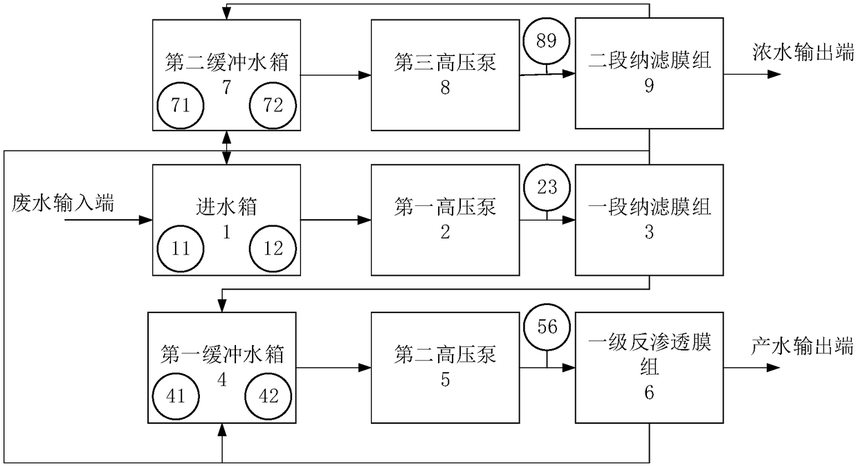
[0058] This case uses this system to treat acidic uranium-containing waste liquid with a uranyl ion concentration of 20g / L and a volume of 1m3.

[0059] The volume of the inlet tank, the first buffer tank and the second buffer tank is set to 1.5m 3 、1.5m 3 、0.5m 3 ; The processing flow rate of the first feedwater pump and the first high-pressure pump is 4m 3 / h, the heads are 30m and 300m respectively; the processing flow rate of the second feed water pump and the second high pressure pump are both 3m 3 / h, the heads are 30m and 400m respectively; the processing flow rate of the third feed water pump and the third high pressure pump are both 1m 3 / h, the heads are 30m and 600m respectively. When the liquid level gauge is at a high level, the water volumes of the inlet tank, the first buffer tank and the second buffer tank are 1.3m respectively 3 、1.0m 3 and 0.3m 3 , when the liquid level gauge is at a low level, the water volumes of the inlet tank, the first buffer tank...

Embodiment example 2

[0063] This case uses this system to treat acidic uranium-containing waste liquid with a uranyl ion concentration of 50g / L and a volume of 1m3.

[0064] The volume of the inlet tank, the first buffer tank and the second buffer tank is set to 2.0m 3 、1.5m 3 、0.7m 3 ; The processing flow rate of the first feedwater pump and the first high-pressure pump is 4m 3 / h, the heads are 30m and 600m respectively; the processing flow rate of the second feed water pump and the second high pressure pump are both 3m 3 / h, the heads are 30m and 400m respectively; the processing flow rate of the third feed water pump and the third high pressure pump are both 1m 3 / h, the heads are 30m and 800m respectively. When the liquid level gauge is at a high level, the water volumes of the inlet tank, the first buffer tank and the second buffer tank are 1.6m respectively 3 、1.2m 3 and 0.4m 3 , when the liquid level gauge is at a low level, the water volumes of the inlet tank, the first buffer tank...


PUM


Abstract

The invention provides a treatment system and method for separating uranyl ions in a concentrated nitric acid system by adopting a membrane technology. The system comprises a water inlet tank 1, a first high-pressure pump 2, a first-section nanofiltration membrane group 3, a first buffer water tank 4, a second high-pressure pump 5, a primary reverse osmosis membrane group 6, a second buffer watertank 7, a third high-pressure pump 8 and a second-section nanofiltration membrane group 9. By adopting the treatment system and method for separating uranyl ions in the concentrated nitric acid systemby adopting the membrane technology, the lower entrapment efficiency of nanofiltration membranes is utilized to make part of uranyl ions to penetrate through a membrane material, the concentration ona water production side is increased, the concentration difference of the water inlet side and the water production side of the separating membranes is reduced, thus the osmotic pressure difference of two sides of the membranes is reduced, and the purpose of reducing operation pressure is achieved; then, the higher entrapment efficiency of reverse osmosis membranes is utilized to improve the removal efficiency of uranyl ions in uranium-bearing waste liquid and make the uranium-bearing waste liquid to meet the treatment requirements.

Description

technical field [0001] The invention relates to the field of uranyl ion treatment, in particular to a treatment system and method for uranyl ion in a concentrated nitric acid system separated by membrane technology. Background technique [0002] At present, in the process of purifying uranium ore with nitric acid, a large amount of acidic uranium-containing waste liquid will be produced. In order to avoid the waste of uranyl ions in uranium-containing waste liquid and the pollution to the environment, it is necessary to separate the acidic uranium-containing waste liquid and enrich the concentration of uranyl ions as much as possible so that it can be reused. [0003] Under acidic conditions, uranyl ions form as cations (UO 2 2+ ) exists in the form of 267 molecular weight. Usually in places where uranium-containing waste liquid is produced, such as uranium mining, uranyl ions are removed, separated and purified by cation exchange. The advantage of this method is that th...

Claims


Application Information

Patent Timeline
Patent Type & Authority Applications(China)
IPC IPC(8): C02F1/44C02F101/20C02F103/10
CPCC02F1/441C02F1/442C02F2101/20C02F2103/10C02F2301/08
Inventor 陈定李志全刘伟明
Owner 北京清核朝华科技有限公司
Why Eureka
Try Eureka