Centrifugal casting mold composite end cover and method for carrying out composite roll centrifugal casting through same

A centrifugal casting and composite technology, which is applied in the field of composite roll centrifugal casting and centrifugal casting composite end caps, can solve the problems of great influence on rolling cost, increase rolling cost, and single function, so as to increase market competition Force, reduce rolling cost, increase the effect of filling area

Active Publication Date: 2015-12-30
江苏环宇冶金科技有限公司
View PDF10 Cites 5 Cited by
  • Summary
  • Abstract
  • Description
  • Claims
  • Application Information

AI Technical Summary

Problems solved by technology

Under normal circumstances, when the composite roll is used to the scrap limit (that is, the working layer is consumed) or when a large defect occurs, the roll will be scrapped as a whole, and the core part of the roll will be treated as scrap steel, which has a great impact on the rolling cost
[0003] At present, in the composite roller centrifugal casting process, ordinary casting end caps are installed at both ends of the centrifugal casting mold, which only have a sealing effect and can prevent liquid metal from splashing, with a single function
The method of centrifugal casting of compound rolls by using the existing ordinary cast end caps usually produces a relatively thin working layer of the compound rolls, which cannot meet the needs of rolling steel production that requires a thick working layer of the rolls. The consumption of the rolls is accelerated, and the scrap rate increases. The rolling cost is reduced; at the same time, in order to increase the high-temperature wear resistance of the working layer of the composite roll, the above-mentioned casting method adds high-hardness carbide elements and elements to improve the stability of the matrix against tempering in the pouring material of the working layer, which increases the production cost.

Method used


Image

  • Centrifugal casting mold composite end cover and method for carrying out composite roll centrifugal casting through same
  • Centrifugal casting mold composite end cover and method for carrying out composite roll centrifugal casting through same
  • Centrifugal casting mold composite end cover and method for carrying out composite roll centrifugal casting through same

Examples


Embodiment Construction

[0032] In the following, the present invention will be further clarified with reference to the accompanying drawings and specific embodiments. It should be understood that these embodiments are only used to illustrate the present invention and not to limit the scope of the present invention. After reading the present invention, those skilled in the art will understand various aspects of the present invention. Modifications in equivalent forms fall within the scope defined by the appended claims of this application.

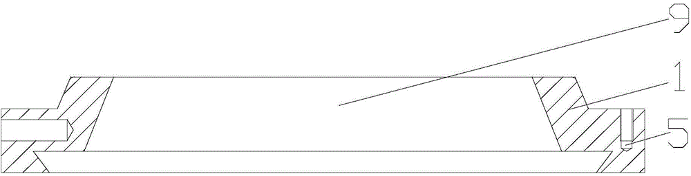
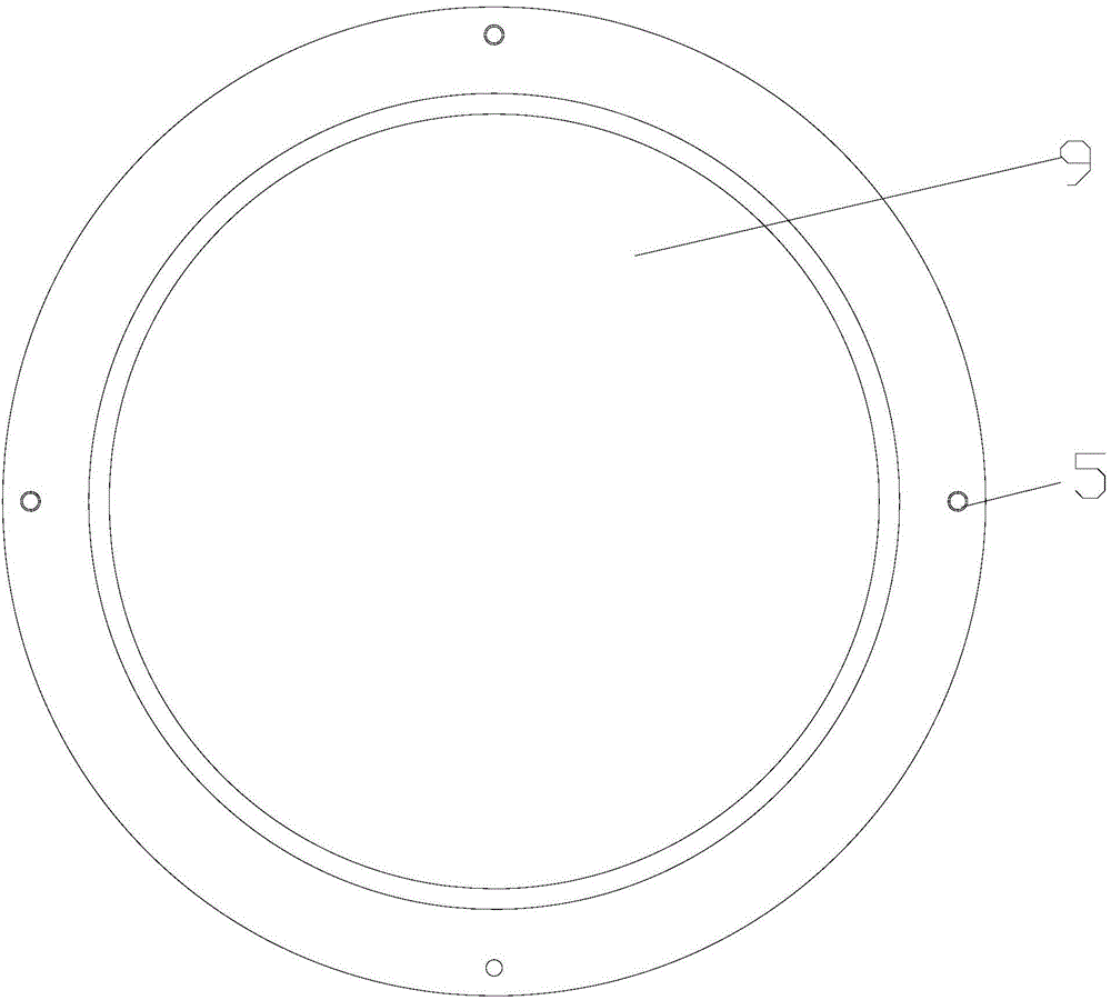
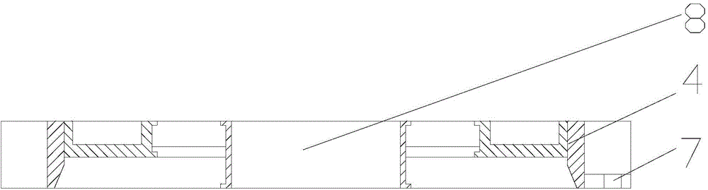
[0033] As attached Figure 1-8 As shown, a centrifugal casting composite end cover includes a casting end cover 1 and an additional end cover 4. The additional end cover 4 is placed above the casting end cover 1, and the two are movably connected by a rotary buckle device . The rotary buckle device includes screw holes 5, bolts 6 and protruding bayonet openings 7 corresponding to each other in number. The screw holes 5 are symmetrically arranged on the two sides of ...


PUM


Abstract

The invention discloses a centrifugal casting mold composite end cover and a method for carrying out composite roll centrifugal casting through the same. The centrifugal casting mold composite end cover comprises a casting mold end cover and an additional end cover. The casting mold end cover and the additional end cover are movably connected through a rotary buckle device composed of screw holes, bolts and protruding clamping openings. The method for carrying out composite roll centrifugal casting through the centrifugal casting mold composite end cover comprises the steps that the centrifugal casting mold composite end cover is installed at the two ends of a metal cast mold, a thickened roll working layer is centrifugally cast, and the roll core portion and neck are statically cast in a mold assembling mode after the additional end cover is dismantled, wherein the specific steps comprise casting sand preparation, casting tool preparation and preheating, metal casting mold coating, liquid metal treatment, working layer centrifugal casting, static casting of the core potion and roll neck, and cooling machining. The centrifugal casting mold composite end cover and the method for carrying out composite roll centrifugal casting through the same have the advantages that installation is easy and convenient, the thickened working layer is formed during centrifugal casting, the roll service life is prolonged, the rejection rate and cost are reduced, and meanwhile casting and machining of the roll core portion and neck are not affected.

Description

Technical field [0001] The invention relates to the technical field of centrifugal casting, in particular to a centrifugal casting type composite end cover and a method for centrifugal casting of a composite roll using the same. Background technique [0002] Centrifugal casting can solidify castings under the action of centrifugal force, and is widely used in the production of various castings, especially in the production of composite rolls. Ordinary composite rolls refer to rolls composed of a working layer and a core (including a roll neck). Some composite rolls also include a transition layer between the working layer and the core. The composite roll can not only meet the requirements of the rolling mill for the wear resistance and thermal fatigue resistance of the roll working layer, but also ensure the strength and toughness of the core and roll neck. The composite roll is the main consumable process part in the steel rolling process, and the main consumable is the working...

Claims


Application Information

Patent Timeline
Patent Type & Authority Applications(China)
IPC IPC(8): B22D13/10B22D13/02
Inventor 吴江
Owner 江苏环宇冶金科技有限公司
Why Eureka
Try Eureka