
Machine tool stand column

A machine tool and column technology, which is applied in the field of machining center components, can solve the problems of affecting the quality and precision of workpieces, low structural strength, poor bearing capacity, etc., and achieve the effect of less processing area, reduced processing area, and low cost of columns

Inactive Publication Date: 2015-12-30
苏州金凡球墨铸铁有限公司
View PDF8 Cites 6 Cited by
  • Summary
  • Abstract
  • Description
  • Claims
  • Application Information

AI Technical Summary

Problems solved by technology

At present, the structural strength of the machine tool column on the market is not high, and the bearing capacity is poor; because the machine tool column itself will vibrate when the workpiece is processed, this will further affect the quality and accuracy of the workpiece, resulting in more workpiece defects

Method used


Image

  • Machine tool stand column
  • Machine tool stand column
  • Machine tool stand column

Examples


Embodiment Construction

[0023] In order to make the object, technical solution and advantages of the present invention clearer, the present invention will be further described in detail below in conjunction with the accompanying drawings and embodiments. It should be understood that the specific embodiments described here are only used to explain the present invention, not to limit the present invention.

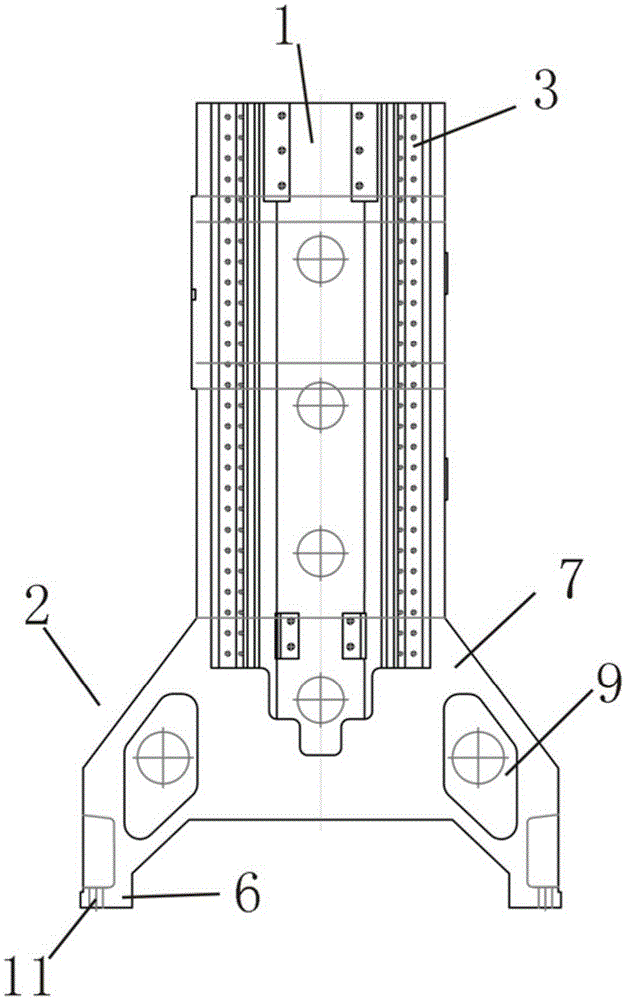
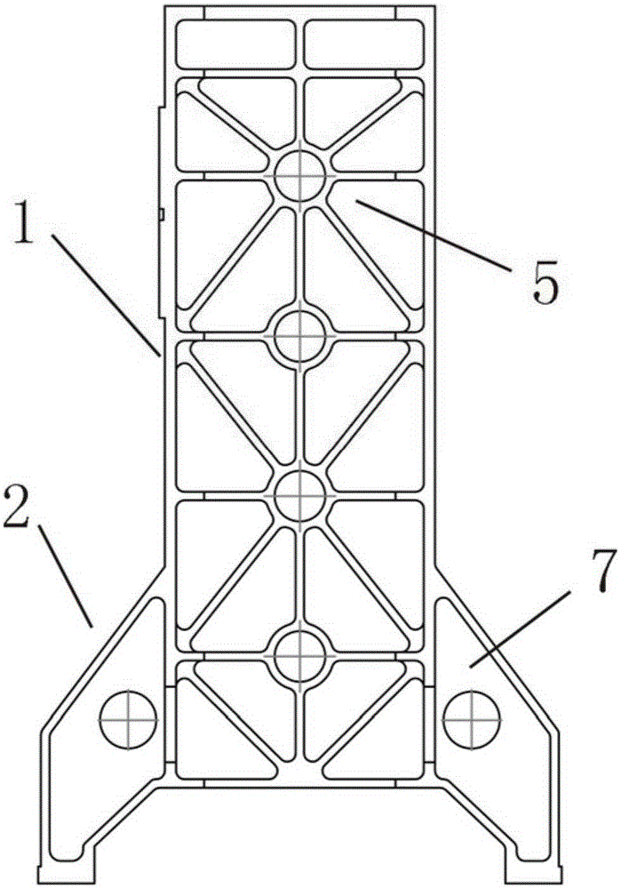
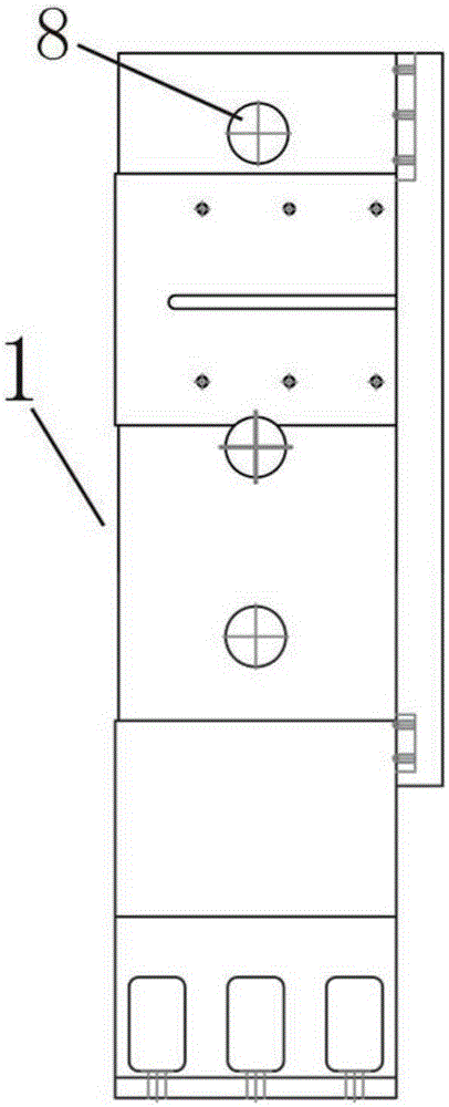
[0024] figure 1 A column for a machine tool is shown, including a column body 1 , a base 2 , a line rail 3 and a top 4 arranged on the outer side of the column body 1 (ie, the front of the machine column) for connecting the spindle head (not shown) of the machine tool. The line rail 3 is parallel and symmetrically arranged on the outer side of the cylinder 1. The line rail 3 can make the machine tool spindle head installed on it move up and down along the line rail 3, thereby realizing the Z-axis movement of the machine tool spindle head. The base 2 of the column of the machine tool includes a con...


PUM


Abstract

The invention discloses a machine tool stand column. The machine tool stand column comprises a column body, a base, linear rails which are arranged on one side of the exterior of the column body and used for connecting a machine tool spindle head and a top used for fixing a counterweight stretcher, a guide chain and a balancing weight; the interior of the column body is provided with a cavity and reinforcing ribs shaped like a Chinese character 'mi'; the base comprises connecting parts used for connecting a machine tool pedestal and a base body arranged between the column body and the connecting parts; the base body symmetrically extends from the two sides of the lower portion of the column body. The machine tool stand column is high in structural strength, large in carrying capacity, high in stability, low in stand column cost, small in machining area and capable of effectively reducing vibration generated when a machine tool machines a workpiece.

Description

technical field [0001] The invention relates to the field of machining center components, in particular to a machine tool column. Background technique [0002] In the existing CNC machining technology, the machine tool is composed of a column, a spindle head, a workbench, a saddle and a base. As an indispensable part of the machine tool, the main function of the column is to enable the spindle head to move up and down and play a supporting role. At present, the structural strength of the machine tool column on the market is not high, and the bearing capacity is poor; because the machine tool column itself will vibrate when the workpiece is processed, this will further affect the quality and accuracy of the workpiece, resulting in more workpiece defects. Contents of the invention [0003] In order to solve the above technical problems, the object of the present invention is to provide a machine tool column. The column of the machine tool has high structural strength, larg...

Claims


Application Information

Patent Timeline
Patent Type & Authority Applications(China)
IPC IPC(8): B23Q1/01
CPCB23Q1/015
Inventor 吴玉进
Owner 苏州金凡球墨铸铁有限公司
Learn More