Drum deburring machine
A technology of deburring machine and deburring mechanism, which is applied to surface polishing machine tools, machine tools suitable for grinding workpiece edges, grinding machines, etc. It can solve problems such as single structure, cumbersome workpiece transportation operations, time-consuming and labor-intensive safety, and achieve Convenient centralized management, convenient collection and transportation, and low manufacturing cost
- Summary
- Abstract
- Description
- Claims
- Application Information
AI Technical Summary
Problems solved by technology
Method used
Image
Examples
Embodiment 1
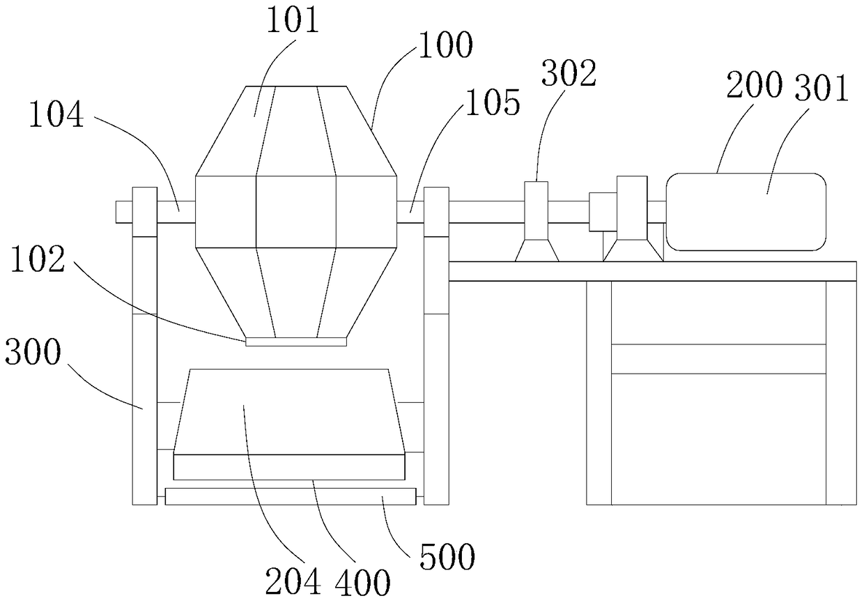
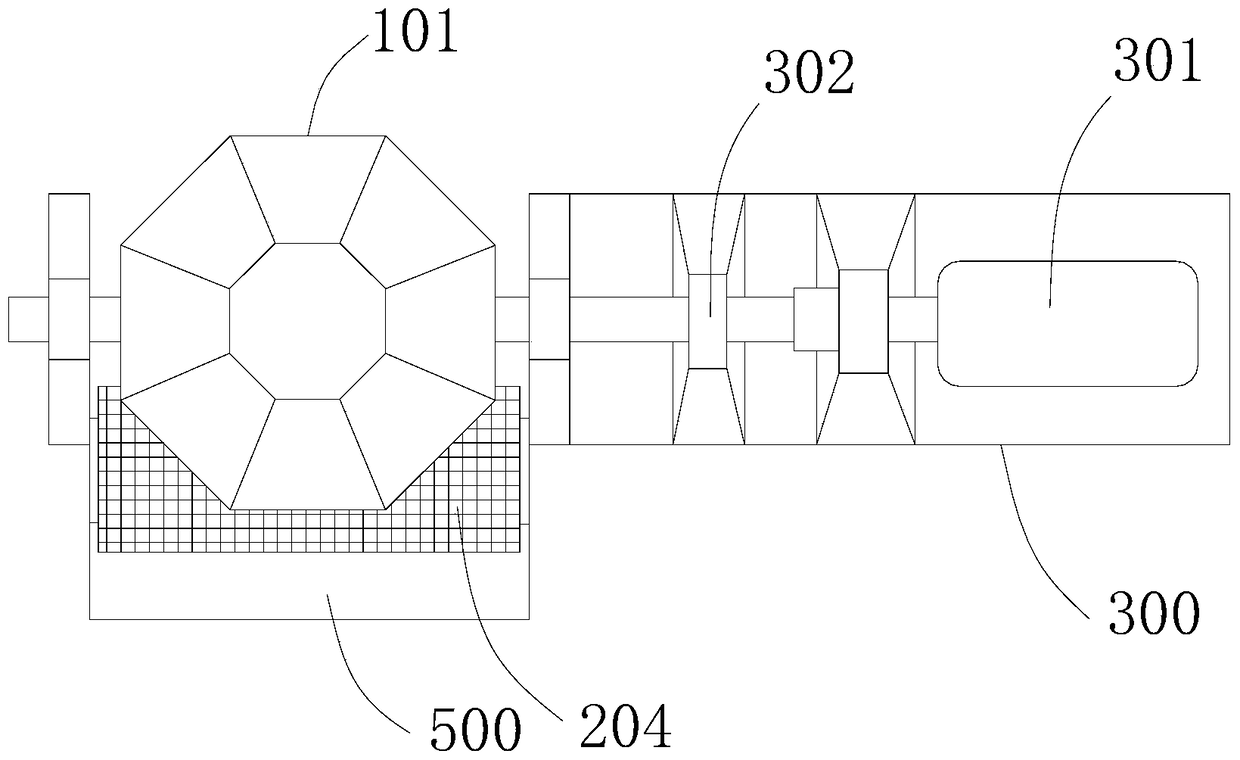
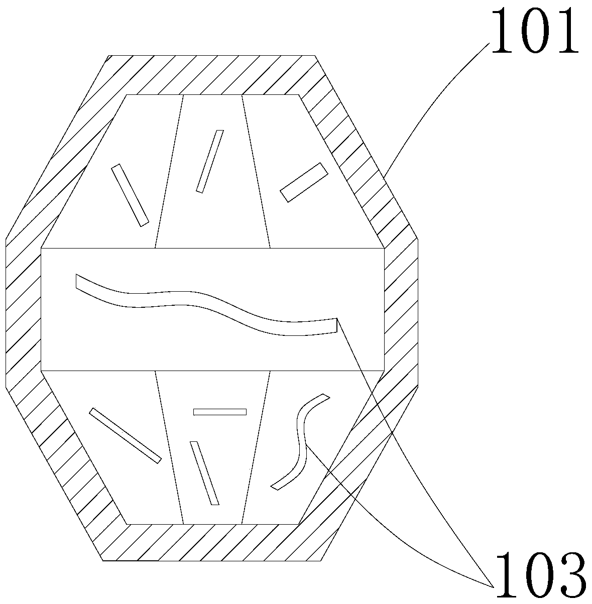
[0046] see Figure 1-5 , this embodiment provides a drum type deburring machine, including a deburring mechanism 100, a transmission mechanism 200 and a mounting frame 300, wherein:
[0047] The deburring mechanism 100 and the transmission mechanism 200 are respectively mounted on the mounting frame 300, the deburring mechanism 100 is rotationally connected to the mounting frame 300, and the input end of the deburring mechanism 100 is fixedly connected to the The output end of the transmission mechanism 200, the transmission mechanism 200 drives the deburring mechanism 100 to rotate relative to the installation frame 300;
[0048] The drum type deburring machine also includes a material guide plate 400 and a cooling tank 500, the material guide plate 400 is located below the deburring mechanism 100, the cooling tank 500 is located below the material guide plate 400, and The material guide plate 400 and the cooling tank 500 are respectively detachably connected to the installa...
Embodiment 2
[0063] see Figure 6-7 , this embodiment also provides a drum type deburring mechanism 100, this embodiment is a further improvement on the basis of the technical solution of the first embodiment, the technical solution described in the first embodiment is also applicable to this embodiment, the embodiment A description of the technical solution will not be described repeatedly, as follows:
[0064] The cooling tank 500 is provided with a filter screen 201, the filter screen 201 is located between the material guide plate 400 and the cooling tank 500, and the filter screen 201 is detachably connected to the cooling tank 500, so as to facilitate the removal of impurities Separated from the workpiece, the subsequent processing of the workpiece is more convenient.
[0065]In a preferred solution of this embodiment, the material guide plate 400 includes two opposite side plates 202 and a bottom plate 203 between the two side plates 202, the bottom plate 203 is fixedly connected t...
PUM
 Abstract
Description
Claims
Application Information
 - R&D
- Intellectual Property
- Life Sciences
- Materials
- Tech Scout
- Unparalleled Data Quality
- Higher Quality Content
- 60% Fewer Hallucinations
Browse by: Latest US Patents, China's latest patents, Technical Efficacy Thesaurus, Application Domain, Technology Topic, Popular Technical Reports.
© 2025 PatSnap. All rights reserved.Legal|Privacy policy|Modern Slavery Act Transparency Statement|Sitemap|About US| Contact US: help@patsnap.com


