Screw conveyor provided with material blocking and cleaning device

A screw conveyor and material cleaning technology, applied in the field of screw conveyors, can solve the problems of personal safety accidents, equipment safety accidents, damage to the bearing seat sealing ring, etc.

Inactive Publication Date: 2015-12-30
NORTHERN HEAVY IND GRP CO LTD
View PDF6 Cites 2 Cited by
  • Summary
  • Abstract
  • Description
  • Claims
  • Application Information

AI Technical Summary

Problems solved by technology

[0002] At present, in metallurgy, electric power, coal, chemical industry, papermaking, building materials and other industries, the spiral reclaimer used for reclaiming materials is on the non-discharging side of the discharge port of the spiral chute, due to the vibration of the equipment, the inertia of material flow, Factors such as splashing and deposition accumulate over time and accumulate more and more materials that cannot be conveyed normally, resulting in the problem that when the amount of deposited materials is too much, the materials will enter the sealing ring at the connection between the spiral groove body and the screw shaft In severe cases, the sealing ring will be damaged by the material, the screw shaft will directly contact with the steel structure of the spiral groove body and the screw shaft will be damaged, and even the material will be squeezed out of the spiral groove body and enter the bearing seat, causing damage to the sealing ring of the bearing seat. More serious equipment safety accidents and personal safety accidents
Most of the current solutions to this problem are to add ordinary steel plates to block materials, but they cannot fundamentally solve the problem of cleaning up the deposited materials that cannot be discharged normally.

Method used


Image

  • Screw conveyor provided with material blocking and cleaning device
  • Screw conveyor provided with material blocking and cleaning device

Examples


Embodiment Construction

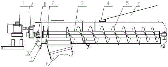
[0012] Referring to the accompanying drawings, a screw conveyor with a material blocking and cleaning device includes a main screw drive 1, a reverse spiral blade 2 for blocking and cleaning materials, a screw shaft 3, a material tank body 4, and a screw blade 5. The reverse spiral blade 2 and spiral blade 5 for feeding and cleaning are welded on the screw shaft 3. After welding, they are loaded into the material tank 4, and the main screw drive 1 is connected to the screw shaft 3 through the reducer A and the bearing seat B. Seal with O-ring D.

[0013] The working principle of the screw conveyor with a blocking and cleaning device is that, using the principle of screw conveying, a reverse spiral blade 2 for blocking and cleaning is added at the accumulated material to convey materials in the opposite direction. , play the role of cleaning the accumulation of materials; on the same screw shaft 3, on the non-discharge side of the discharge port F, that is, the position of the ...


PUM


Abstract

A screw conveyor provided with a material blocking and cleaning device comprises a main screw drive, a material blocking and cleaning reverse screw blade, a screw shaft, a material trough body and a screw blade, wherein the material blocking and cleaning reverse screw blade and the screw blade are welded on the screw shaft and mounted into the material trough body after welding, and the main screw drive and the screw shaft are connected through a speed reducer A and a bearing seat B and sealed through a seal ring D; the main screw drive is started, the screw shaft drives the screw blade to rotate, the material blocking and cleaning reverse screw blade rotates synchronously with the screw shaft, materials enter the material trough body from a material inlet C, and when the materials are accumulated in a material accumulation position E, the material blocking and cleaning reverse screw blade conveys the accumulated materials synchronously in an opposite direction into a material discharge opening F. The screw conveyor can realize both the material blocking function and the accumulated material cleaning function, is high in continuity and is applied to the technical fields of metallurgy, electric power, chemical engineering, coal, papermaking and building materials.

Description

technical field [0001] The invention relates to a screw conveyor with a material stopper and a material cleaning device, which is applied to a top-stack spiral take-up circular stacker and reclaimer in the technical fields of metallurgy, electric power, chemical industry, coal, papermaking and building materials. Background technique [0002] At present, in metallurgy, electric power, coal, chemical industry, papermaking, building materials and other industries, the spiral reclaimer used for reclaiming materials is on the non-discharging side of the discharge port of the spiral chute, due to the vibration of the equipment, the inertia of material flow, Factors such as splashing and deposition accumulate over time and accumulate more and more materials that cannot be conveyed normally, resulting in the problem that when the amount of deposited materials is too much, the materials will enter the sealing ring at the connection between the spiral groove body and the screw shaft ...

Claims


Application Information

Patent Timeline
Patent Type & Authority Applications(China)
IPC IPC(8): B65G33/24B65G33/30B65G65/22
Inventor 冯学慧郭天纲费勇王新雷范磊卢士先杜海滨张庭亮任志刚唐亮张龙
Owner NORTHERN HEAVY IND GRP CO LTD
Why Eureka
Try Eureka