
control panels for elevators

A control panel, elevator technology, used in elevators in buildings, non-mechanical transmission-operated locks, building locks, etc.

Active Publication Date: 2020-06-19
KONE CORP
View PDF7 Cites 0 Cited by
  • Summary
  • Abstract
  • Description
  • Claims
  • Application Information

AI Technical Summary

Problems solved by technology

The locking of the control panel is not necessarily sufficiently effective to prevent unauthorized opening of the control panel

Method used


Image

  • control panels for elevators
  • control panels for elevators
  • control panels for elevators

Examples


Embodiment Construction

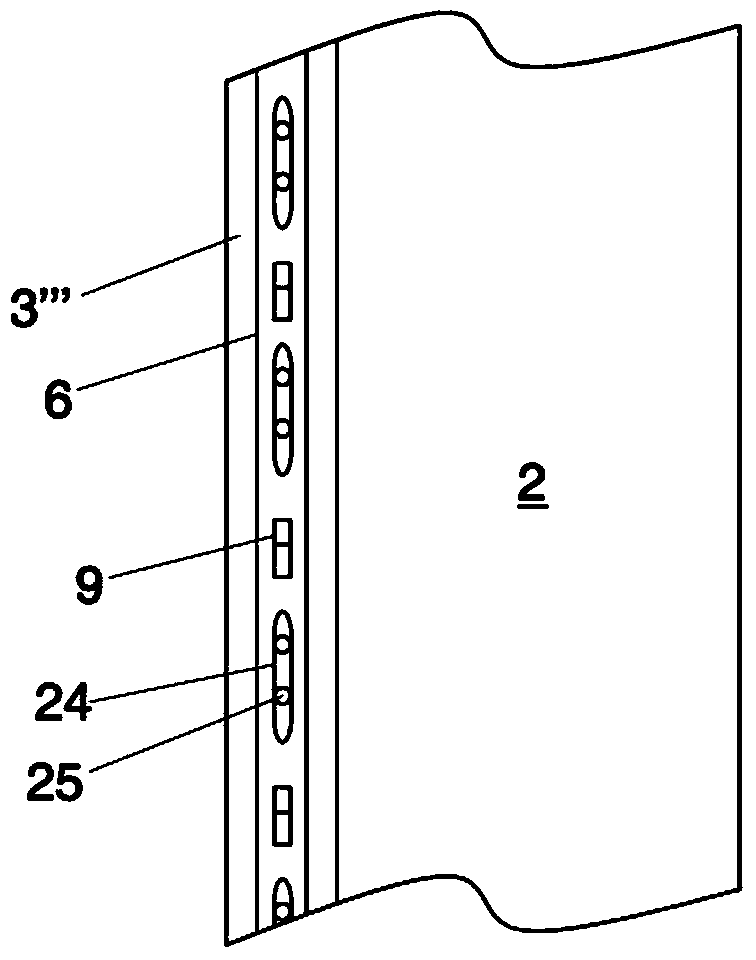
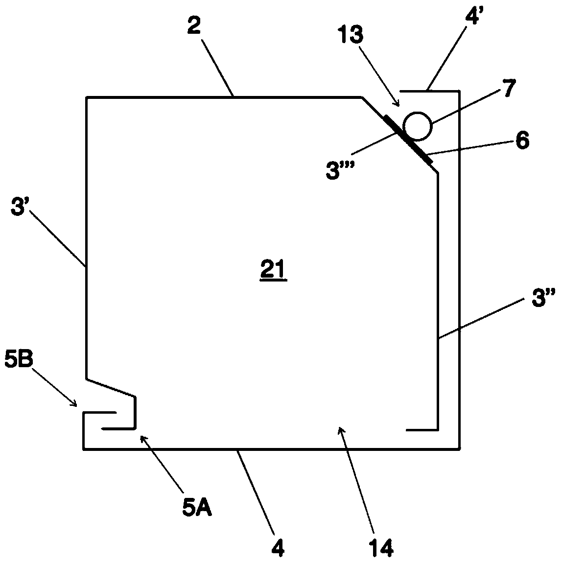
[0028] figure 1 Shown is an elongated control panel 1 intended to be arranged in a side door frame of a landing door of a machine room-less elevator. A landing door is a door that closes the entrance from the floor level to the elevator shaft. Elevator passengers can transfer into the elevator car and leave the elevator car via the landing door when the elevator car is at a floor level adjacent to the landing door. At other times, the landing doors can be opened by a special service key, in which case maintenance personnel can enter the elevator shaft via the open landing doors.

[0029] Unlike control panels known in the prior art, figure 1 The door 4 of the control panel does not have a separate lock hole, but instead the outer surface of the control panel forms an unbroken machined surface as part of the door frame. As a result, the control panel is better protected against vandalism. The undamaged exterior surface also improves the appearance of the door frames of the ...


PUM


Abstract

The invention relates to a control panel (1) for an elevator comprising a base (2), side walls (3', 3"), a door (4) and a locking mechanism (6, 7) for locking and unlocking the door , 8, 9, 10, 11). The locking mechanism includes a catch device (6), which is adapted to be movable between a locked position and a release position, and an electrically controllable actuator (7) connected to the catch device ), the actuator is adapted to move the capture device (6) in response to a wireless control signal.

Description

technical field [0001] The invention relates to the structure of a control panel for an elevator. Background technique [0002] Elevators include various electrical components, such as electronic equipment plug-ins, relays, switches, safety devices, etc., through which the operation of the elevator is controlled. [0003] Most of the electrical components of the elevator are arranged in a separate control panel from which control and power supply cables run to different parts of the elevator system. The main switches of the elevator and the elevator control electronics, in particular, are usually located in the control panel. Manually operated devices can also be provided in the control panel, by means of which the elevator is operated during service and maintenance and when rescuing passengers stuck in the elevator car in case of failure. [0004] The control panel is traditionally located in a separate machine room, access to which is limited. Today, however, many eleva...

Claims


Application Information

Patent Timeline
Patent Type & Authority Patents(China)
IPC IPC(8): B66B1/34
CPCB66B1/3423B66B11/001B66B13/306B66B1/465E05B19/14E05B47/0001E05C9/02
Inventor A.黑凯嫩
Owner KONE CORP
Learn More