
Yarn stand of warping machine

A technology of warping machine and creel, applied in the field of creel and creel of warping machine, can solve the problems such as the inability to automatically adjust the distance, the large space occupied by creel, and the degree of space utilization, so as to achieve space utilization rate. High, easy to adjust, high degree of intelligence effect

Inactive Publication Date: 2015-12-30
邓红梅 +2
View PDF7 Cites 9 Cited by
  • Summary
  • Abstract
  • Description
  • Claims
  • Application Information

AI Technical Summary

Problems solved by technology

[0004] Although the yarn creel disclosed in this patent can prevent the bobbin from falling off, the fixing effect is very good, and the V-shaped elastic part is simple to process and low in cost, but the distance between adjacent supports in the creel cannot be automatically adjusted. The creel occupies a large space and the space utilization rate is high. Therefore, it is necessary to design a creel for the warping machine.

Method used


Image

  • Yarn stand of warping machine
  • Yarn stand of warping machine
  • Yarn stand of warping machine

Examples


specific Embodiment approach

[0036] The following are specific embodiments of the present invention and in conjunction with the accompanying drawings, the technical solutions of the present invention are further described, but the present invention is not limited to these embodiments.

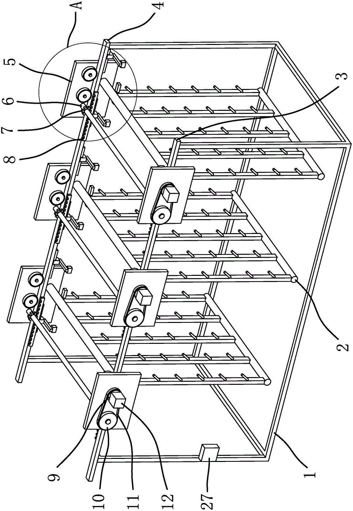
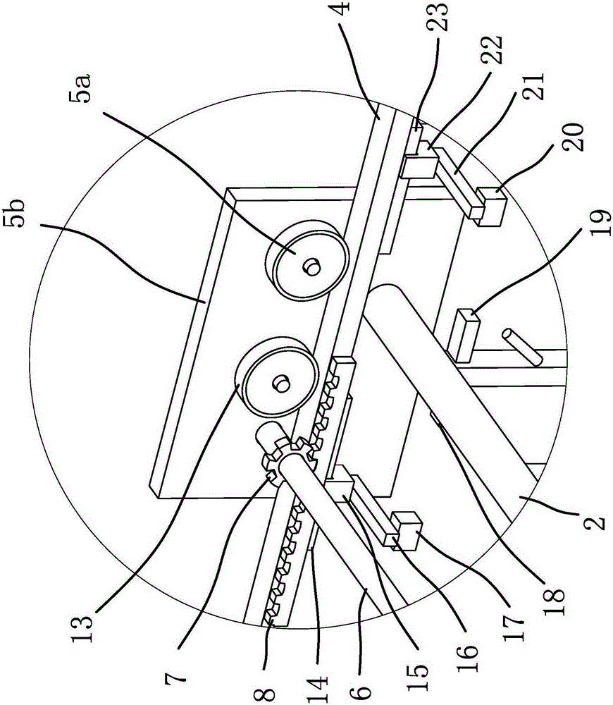
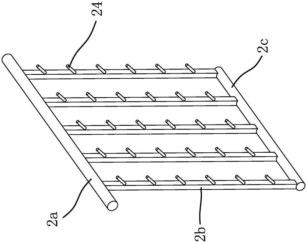
[0037] Such as figure 1 , figure 2 , image 3As shown, the creel 2 of the warping machine includes a mounting frame 1, and the mounting frame 1 has a mounting beam 1 4 and a mounting beam 2 3 parallel to each other, and the mounting beam 1 4 and the mounting beam 2 3 are welded fixed on the mounting frame 1 in a manner; the creel 2 includes an upper cross bar 2a, a lower cross bar 2c and a number of vertical bars 2b. In this embodiment, the number of vertical bars 2b is five, and the vertical bars 2b are fixed There is a positioning rod 24 for setting the coil; the upper end of the vertical bar 2b is fixedly connected with the upper horizontal bar 2a, and the upper end of the vertical bar 2b is fixedly connected with th...


PUM


Abstract

The invention provides a yarn stand of a warping machine, belonging to the technical field of textiles. By adopting the yarn stand of warping machine, the technical problems that the distance between adjacent supports of the existing yarn stand cannot be automatically adjusted, the yarn stand is large in occupied space, the space utilization rate is low and the like are solved. The warping machine comprises an installation rack, wherein the installation rack is provided with an installation beam I and an installation beam II which are parallel to each other. The yarn stand comprises an upper beam, a lower beam, and a plurality of vertical rods, wherein the installation beam I and an installation beam II are respectively provided with sliding seats capable of sliding along the length direction, two ends of the upper beam are fixed on the sliding seats, each sliding seat comprises a sliding plate and a sliding wheel, the sliding wheel is rotatably connected to the sliding plate, the circumferential surface of the sliding wheel is propped against the upper surface of the installation beam I or an installation beam II, racks are fixed on the installation beam I and an installation beam II, gears meshed with the racks are arranged on the sliding plates, and the gears on the installation beam I and an installation beam II are connected by a transmission shaft and synchronously rotate. The yarn stand of warping machine has the advantages of high space utilization rate, and convenience in adjusting.

Description

technical field [0001] The invention belongs to the technical field of textiles, and relates to a creel, in particular to a creel of a warping machine. Background technique [0002] Various textile fibers are processed into products of a certain fineness, which are used for weaving, rope making, thread making, knitting and embroidery, etc. The warping machine is a machine that winds the yarn on the coil on the pan head. The role played by the warping machine in textile manufacturing is irreplaceable. The warping machine works under the control of the speed regulating system to ensure that the tension of all the yarns wound on the reel remains consistent, that is, all yarns should be parallel and evenly Distributed on the warp beam, and keep as much as possible during the warping process, otherwise, it will cause an increase in the number of breaks in the weaving process, and make the structure of the woven fabric disordered. The support for placing the coil becomes a creel, ...

Claims


Application Information

Patent Timeline
IPC IPC(8): D02H1/00
Inventor 孙维
Owner 邓红梅
Learn More