Construction Method of Double Shear Wall Formwork Support Formwork at Deformation Joints

A construction method and deformation joint technology, which is applied in the direction of the formwork/formwork/work frame, the joints of the formwork/formwork/work frame, walls, etc., and can solve the problem that the filling materials such as benzene boards cannot be removed or the removal is not clean and time-consuming Problems such as filling materials such as benzene board and affecting the structure and function of deformation joints have been solved, so as to achieve the effect that the overall formwork system supported by airbags is not easy to deform, avoid residual garbage, and the overall formwork system supported by airbags is stable

Active Publication Date: 2016-11-09
SHANDONG HUABANG CONSTR GRP
View PDF6 Cites 0 Cited by
  • Summary
  • Abstract
  • Description
  • Claims
  • Application Information

AI Technical Summary

Problems solved by technology

[0002] According to the needs of structural design, buildings are usually equipped with deformation joints, and shear wall structures on both sides of the deformation joints are also very common in buildings. However, due to the small width of the deformation joints, the support and Demolition often has a certain degree of construction difficulty during structural construction
The traditional formwork construction method is to construct the shear wall on one side first, and then fill the deformation joints with fillers such as benzene plates when constructing the shear wall on the other side. It is not easy to control, and at the same time, the fillers such as benzene boards cannot be removed or the removal is not clean. Even if the existing shear walls on both sides of individual deformation joints are constructed at the same time, the fillers or shear wall formwork used as supports in the deformation joints cannot Remove or remove cleanly, thus directly affecting the structural function of deformation joints

Method used


Image

  • Construction Method of Double Shear Wall Formwork Support Formwork at Deformation Joints
  • Construction Method of Double Shear Wall Formwork Support Formwork at Deformation Joints
  • Construction Method of Double Shear Wall Formwork Support Formwork at Deformation Joints

Examples


Embodiment Construction

[0059] The technical solutions of the present invention will be described in detail below through specific examples.

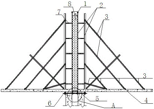
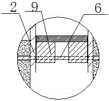
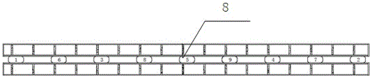
[0060] The construction method of the double shear wall formwork formwork at the deformation joints of the present invention has the following steps: construction preparation → setting out and positioning → production and installation of the formwork at the deformation joints and the airbag bracket platform → production and installation of steel bars for the shear walls → concrete limit Strip installation→wall base cleaning→inside (away from the deformation joint side) and floor formwork installation→outside (close to the deformation joint side) overall formwork fabrication and installation→high-pressure airbag placement→high-pressure airbag pressurization→shear wall head formwork installation → Fabrication and installation of temporary cover plates for formwork at deformation joints → Concrete pouring and maintenance → Deflation and removal of high-pressure ai...


PUM


Abstract

The invention belongs to the technical field of construction of building deformation joints and particularly relates to a construction method of a double-shear wall template formwork at a deformation joint. Shear wall template support systems at two sides of the deformation joint are deeply researched and analyzed, a high-pressure hollow airbag is used as shear wall template supports at the two sides in the deformation joint, and the airbag can be inflated to form a pressure-proof rigid body to be combined with shear wall templates at the two sides and steel tube supports at the outer side of the deformation joint to form a steady two-side shear wall template support system, thereby realizing simultaneous support of the shear wall templates at the two sides of the deformation joint; and after the shear wall templates are dismantled, the high pressure airbag can be deflated to reduce the pressure so as to be smoothly removed, and then the templates at the inner side of the deformation joint can be conveniently lifted out sequentially, so that residual wastes of building construction do not exist in the deformation joint and the materials can be recycled many times.

Description

technical field [0001] The invention belongs to the technical field of building deformation joint construction, in particular to a construction method for supporting formwork of a double shear wall formwork at a deformation joint. Background technique [0002] According to the needs of structural design, buildings are usually equipped with deformation joints, and shear wall structures on both sides of the deformation joints are also very common in buildings. However, due to the small width of the deformation joints, the support and Demolition often has certain construction difficulties during structural construction. The traditional formwork construction method is to construct the shear wall on one side first, and then fill the deformation joints with fillers such as benzene plates when constructing the shear wall on the other side. It is not easy to control, and at the same time, the fillers such as benzene boards cannot be removed or the removal is not clean. Even if the ...

Claims


Application Information

Patent Timeline
Patent Type & Authority Patents(China)
IPC IPC(8): E04B2/84E04G11/08E04G17/14E04G15/00
Inventor 王晋董玉罡刘广钶李兴艳孟明
Owner SHANDONG HUABANG CONSTR GRP
Why Eureka
Try Eureka