A Tensor Apparent Conductivity Measurement Method

A technology of apparent conductivity and measurement method, applied in the field of electromagnetic detection, which can solve problems such as apparent resistivity distortion and measurement area limitation

Active Publication Date: 2017-07-25
CENT SOUTH UNIV
View PDF4 Cites 0 Cited by
  • Summary
  • Abstract
  • Description
  • Claims
  • Application Information

AI Technical Summary

Problems solved by technology

This method is limited by the measurement area. In the non-far area, the calculated apparent resistivity is seriously distorted; the apparent resistivity of the whole area of ​​the frequency domain electromagnetic method and the wide area apparent resistivity of the wide area electromagnetic method are calculated by iterative method. Its calculation formula introduces parameters such as field source and sending and receiving distance, and the calculation process needs to be iterative

Method used


Image

  • A Tensor Apparent Conductivity Measurement Method
  • A Tensor Apparent Conductivity Measurement Method
  • A Tensor Apparent Conductivity Measurement Method

Examples


Embodiment Construction

[0065] The present invention will be further described below in conjunction with the accompanying drawings and specific embodiments.

[0066] When observing the natural electromagnetic field, the implementation of the tensor apparent conductivity measuring method of the present invention comprises the following steps:

[0067] (1) Observation design: Determine the observation target and depth range, determine the measurement frequency range according to the actual exploration depth requirements and the background conductivity of the survey area, and determine the observation time length and signal sampling rate of a single measurement point according to the required measurement frequency;

[0068] (2) Survey line deployment: design survey lines and survey points according to the detection target and the scope of the survey area;

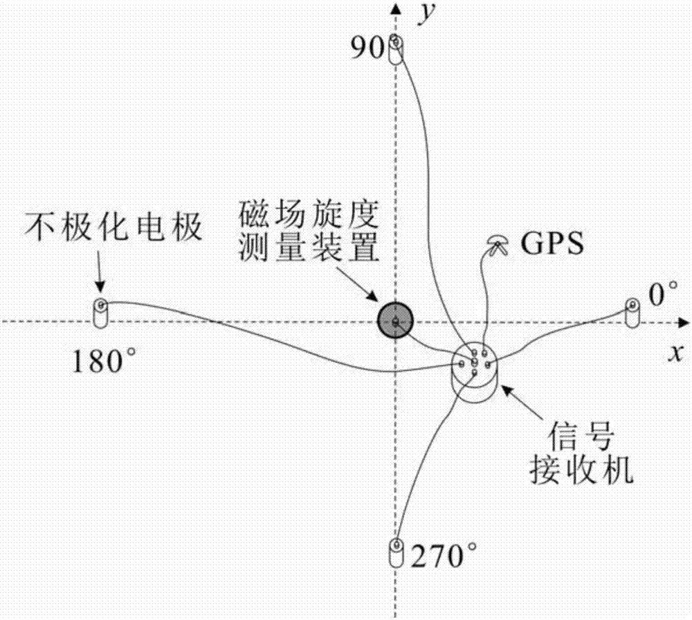
[0069] (3) Device layout: Determine the number of measuring points for each group of observation and layout according to the design and the number o...


PUM


Abstract

The invention provides a tensor apparent conductivity measurement method. The tensor apparent conductivity measurement method comprises the following steps that 1, an orthogonal electric field E and a curl M of a magnetic field are simultaneously measured on the surface of ground or underground; 2, the tensor apparent conductivity is calculated according to observation data through a formula (please see the formula in the specification), wherein E and M represents observation matrices containing multiple sets of the E and the M. According to the tensor apparent conductivity measurement method, a measured electromagnetic field can adopt a natural electromagnetic field, and also can adopt an electromagnetic field generated through motivation of an artificial field source; the electromagnetic field can be measured at a frequency domain, changes of the tensor apparent conductivity along with the frequency are obtained, and frequency domain sounding is performed; the electromagnetic field also can be measured at a time domain, changes of the tensor apparent conductivity along with time are obtained, and time domain electromagnetic sounding is performed; the calculation formula does not need to make plane wave hypothesis, is also set up on the condition of a non-plane wave field source and is not limited by the field source conditions; the apparent conductivity calculation formula is simple and does not need iteration or parameters such as a field source position and a sending and receiving distance.

Description

technical field [0001] The invention relates to an electromagnetic detection method in the field of survey geophysics, in particular to a method for measuring tensor apparent conductivity by observing electric field and magnetic field curl. Background technique [0002] In the field of reconnaissance geophysical electromagnetic method, there are many methods of electromagnetic field measurement and apparent resistivity (reciprocal of apparent conductivity) calculation methods, but there are still certain defects and deficiencies. For example, the magnetotelluric method measures two sets of natural electromagnetic fields orthogonal to each other, and uses the tensor estimation formula to calculate the Carnia apparent resistivity; an important assumption of this apparent resistivity calculation method is that the field source is a plane wave, and in the area containing interference In the actual measurement of , due to the existence of humanistic noise, this assumption is no l...

Claims


Application Information

Patent Timeline
Patent Type & Authority Patents(China)
IPC IPC(8): G01V3/08
Inventor 汤井田周聪原源
Owner CENT SOUTH UNIV
Why Eureka
Try Eureka