Complex Protection Element

A technology for protecting components and components, which is applied in the direction of electrical components, battery overvoltage protection, emergency protection devices, etc., and can solve problems such as inability to realize the protection circuit function

Inactive Publication Date: 2015-12-30
SMART ELECTRONICS CO LTD
View PDF15 Cites 1 Cited by
  • Summary
  • Abstract
  • Description
  • Claims
  • Application Information

AI Technical Summary

Problems solved by technology

Since the current cannot be cut off, the protection element cannot realize the function of protecting the circuit and the circuit components on the circuit

Method used


Image

  • Complex Protection Element
  • Complex Protection Element
  • Complex Protection Element

Examples


Embodiment Construction

[0039] Embodiments of the present invention will be described in detail below with reference to the drawings.

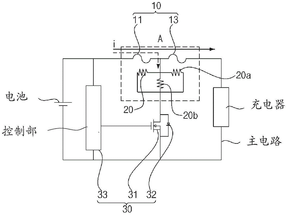
[0040] figure 1 It is a circuit diagram for explaining the use state of the composite protection element of this invention. refer to figure 1 , the composite protection element of the present invention protects the circuit and components connected to the main circuit under abnormal conditions by fusing the fusible element 10 connected to the main circuit.

[0041] The type of the main circuit to which the composite protection element of the present invention is applied is not particularly limited, and the main circuit may be a charging circuit for charging a battery.

[0042] On the above-mentioned main circuit, a battery (battery) and a charger (charger) are connected to the fusible element 10 . Specifically, the main circuit may include a plurality of resistance elements 20, 20a, 20b, and a switching element 30 connected to the plurality of resistance elements 2...


PUM


Abstract

To provide a complex protection element in which cohesion of a fusible element is induced by a circular or oval fusing induction part disposed just below the fusible element so as to improve fusing efficiency. A complex protection element includes: a substrate; at least one pair of resistive terminals provided on the substrate; a pair of fuse terminals provided on the substrate; at least one resistive element provided on the resistive terminals; one fusible element provided on the fuse terminals; a fusing induction part disposed just below the central region of the fusible element to concentrate heat upon the fusible element when the resistive element generates heat; and a switching element controlling flow of current to the resistive element if overvoltage is applied. The fusing induction part is formed in a circular or oval shape so that, when the fusible element is melted, the molten fusible element is cohered in the centripetal direction.

Description

technical field [0001] The present invention relates to a composite protection element, and more particularly, to a composite protection element that can be used to protect circuits and circuit elements provided in the circuits, thereby preventing the circuits and circuit elements from overcurrent and overvoltage. The composite protective element of the present invention has improved thermal characteristics by utilizing a thin-film printed resistive element mounted on the opposite side of the fusible element or placed directly below the fusible element to generate heat, enabling ultra-miniature product design and simplifying the manufacturing process. Background technique [0002] The non-recovery protection element responds to excessive heating due to overcurrent or high ambient temperature on the protected equipment. In order to protect the safety of the equipment, it operates at the specified reaction temperature and cuts off the circuit. For example, one of the protecti...

Claims


Application Information

Patent Timeline
Patent Type & Authority Applications(China)
IPC IPC(8): H01H85/046
CPCH01H85/046H01H37/761H01H85/463H01H2085/466H02H3/023H02H3/10H02H3/202H01H83/20H02H3/087H02J7/00308H02H7/18H02H9/042H01H37/043H02H9/041H02H5/041H01H61/02
Inventor 姜斗园金铉昌金桄范尹生守权赫帝
Owner SMART ELECTRONICS CO LTD
Why Eureka
Try Eureka