
Production technology for dynode shell

A production process, dynode technology, applied in the manufacture of ships or leading wires, etc., to achieve high resistance to ion bombardment, solve the effect of uniformity of film formation, and improve performance

Inactive Publication Date: 2015-12-30
LANZHOU INST OF PHYSICS CHINESE ACADEMY OF SPACE TECH
View PDF3 Cites 2 Cited by
  • Summary
  • Abstract
  • Description
  • Claims
  • Application Information

AI Technical Summary

Problems solved by technology

[0003] Aiming at the deficiencies of the prior art, the present invention proposes a production process for the dynode shell, which can meet the coating requirements of the electron multiplier dynode, and effectively solve the problems of film formation uniformity and stability in the dynode coating.

Method used


Image

  • Production technology for dynode shell
  • Production technology for dynode shell
  • Production technology for dynode shell

Examples


Embodiment Construction

[0018] The present invention will be described in detail below, and the description in this part is only exemplary and explanatory, and should not have any limiting effect on the protection scope of the present invention.

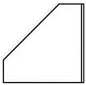
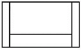
[0019] Such as Figure 1-5 The production process of a dynode shell shown includes the following steps:

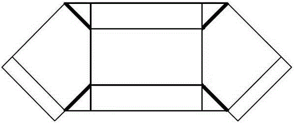
[0020] (1) Liner processing: According to the plane design drawing of the electron multiplier dynode shell, the plane liner is processed, the material is 304 stainless steel, the thickness is 0.1mm, and the surface roughness of the plane liner is required to be 15nm. Use laser beam to cut out folding lines, such as figure 1 As shown, the thick black solid line should be cut through, and the thin solid line should be cut;

[0021] (2) Clean the inner lining: put the No. 304 stainless steel inner lining into a clean container, rinse it with deionized water, and then ultrasonically clean the No. 304 stainless steel inner lining with analytical pure aceto...


PUM


Abstract

The invention discloses a production technology for a dynode shell. The technology includes the steps of 1, machining a lining piece, wherein the lining piece is machined according to a plane drawing of the dynode shell of an electron multiplier, folding lines are marked on the lining piece, and it is guaranteed that the lining piece corresponds to the structure of the dynode shell after being folded; 2, cleaning the lining piece; 3, plating the surface of the lining piece with a film with a secondary electron emission function so as to form a dynode shell piece structure; 4, forming the dynode shell of the electron multiplier, wherein the dynode shell piece structure is folded along the folding lines designed in advance to form the dynode shell. The technology can meet the film plating requirement of a dynode of the electron multiplier and effectively solve the problems of poor film formation uniformity and stability in dynode film plating.

Description

technical field [0001] The invention relates to the technical field of electron multiplier manufacturing, in particular to a production process of a dynode shell. Background technique [0002] The performance of the electron multiplier determines the service life of the atomic clock, and the coating on the inner surface of the dynode is the core technology of the electron multiplier. The current coating method is to coat the molded dynode shell, but the dynode shell has a tank structure, and the coating cannot make the inner and outer surfaces of the dynode shell evenly formed, which directly affects the performance of the electron multiplier and cannot meet the requirements. Electron multiplier secondary electron emission function thin film plating requirements. Contents of the invention [0003] Aiming at the deficiencies of the prior art, the present invention proposes a production process for the dynode shell, which can meet the coating requirements of the electron mu...

Claims


Application Information

Patent Timeline
Patent Type & Authority Applications(China)
IPC IPC(8): H01J9/24
Inventor 李晨李得天王多书曹生珠张玲丁磊
Owner LANZHOU INST OF PHYSICS CHINESE ACADEMY OF SPACE TECH
Learn More