

Flux-weakening control method and flux-weakening control device
A technology of field weakening control and reference voltage, applied in the direction of speed/torque control of a single motor, which can solve the problems of inability to completely eliminate current jumping, unstable speed fluctuations, and inability to naturally smooth the field weakening control of permanent magnet synchronous motors. Achieve high resistance, improve stability, and eliminate the effect of current jumping
- Summary
- Abstract
- Description
- Claims
- Application Information
AI Technical Summary
Problems solved by technology
Method used
Image

Examples
Embodiment 1
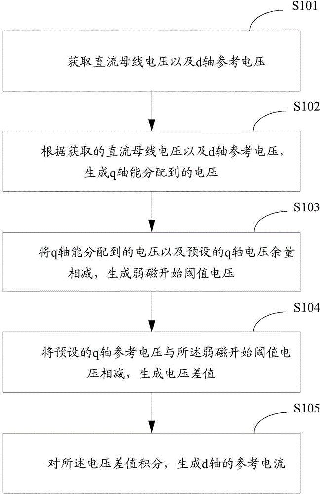
[0026] figure 1 It is a flow chart of the implementation of the field weakening control method provided by the embodiment of the present invention, which is described in detail as follows:
[0027] In step S101, the DC bus voltage and the d-axis reference voltage are acquired;
[0028] In step S102, according to the acquired DC bus voltage and the d-axis reference voltage, generate the voltage that can be allocated to the q-axis;
[0029] In step S103, the voltage that can be allocated to the q-axis and the preset q-axis voltage margin are subtracted to generate a field weakening start threshold voltage;
[0030] In step S104, subtracting the preset q-axis reference voltage from the threshold voltage for starting the field weakening to generate a voltage difference;
[0031] In step S105, the voltage difference is integrated to generate a d-axis reference current.
[0032] Wherein, the reference current of the d-axis is generated by integrating the voltage difference, speci...
Embodiment 2
[0039] The embodiment of the present invention mainly describes the implementation process of step S102, which is described in detail as follows:
[0040] According to the obtained DC bus voltage, the d-axis reference voltage and the pre-configured data table, the voltage that can be assigned to the q-axis is generated.
[0041] Wherein, before the obtained DC bus voltage, d-axis reference voltage and pre-configured data table, it also includes:
[0042] A data table is configured, the data table includes a quantized value and a coefficient corresponding to the quantized value, and the quantized value is a value quantized by a ratio of the d-axis reference voltage to the DC bus voltage.
[0043] In the embodiment of the present invention, a transformed and simple look-up table algorithm is adopted, which occupies less time of the MCU and has strong real-time performance.
Embodiment 3
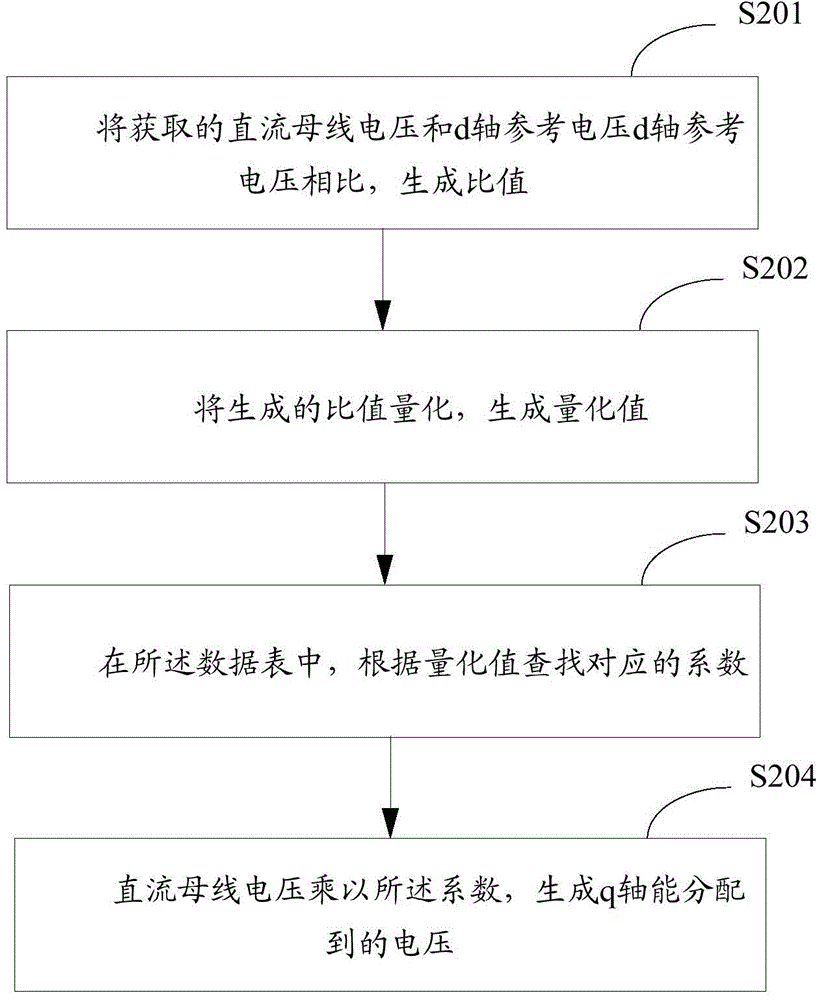
[0045] figure 2 It is a flow chart of the implementation of step S103 of the field weakening control method provided by the embodiment of the present invention, and is described in detail as follows:
[0046] In step S201, comparing the acquired DC bus voltage with the d-axis reference voltage d-axis reference voltage to generate a ratio;
[0047] In step S202, the generated ratio is quantized to generate a quantized value;
[0048] In step S203, in the data table, look up the corresponding coefficient according to the quantization value;
[0049] In step S204, the DC bus voltage is multiplied by the coefficient to generate a voltage that can be allocated to the q-axis.
[0050] In the embodiment of the present invention, the converted and simple look-up algorithm is used to find the corresponding coefficient according to the quantized value, and the voltage that can be allocated to the generated q-axis can be quickly obtained, so the real-time performance is strong, and th...
PUM
 Abstract
Description
Claims
Application Information