Phase calibration structure of magnetic resonance radio frequency power amplifier

A radio frequency power and phase calibration technology, applied to power amplifiers, high-frequency amplifiers, improved amplifiers to improve efficiency, etc., can solve problems such as difficulty in ensuring consistency, deviation between output results and expected design results, and high power, to achieve Best synthesis efficiency, phase consistent effect

Inactive Publication Date: 2015-12-30
XINGAOYI MEDICAL EQUIP CO LTD
View PDF7 Cites 2 Cited by
  • Summary
  • Abstract
  • Description
  • Claims
  • Application Information

AI Technical Summary

Problems solved by technology

Theoretically, we hope that after the input signals of N channels pass through the power amplifier tube, the output signals obtained are also completely equal. Each input signal and output signal have two variables, one is the gain and the other is the phase; but in fact, due to various power The inconsistency of the amplifier tubes, especially the power of the nuclear magnetic resonance radio frequency power amplifier tubes is relatively large, and a single power amplifier tube can reach more than 1.5KW, so it is difficult to ensure that when the amplitude and phase of the input signal of each power amplifier tube remain the same, The phase and amplitude of the obtained output signal are also consistent
Therefore, although the phase and amplitude of the input signal are the same, after passing through the power amplifier tube, the phase and amplitude are different, and the different signals are then vector synthesized by the synthesizer, resulting in the final output result and the expected design result produce large deviation

Method used


Image

  • Phase calibration structure of magnetic resonance radio frequency power amplifier
  • Phase calibration structure of magnetic resonance radio frequency power amplifier

Examples


Embodiment Construction

[0010] The present invention will be further described in detail below in conjunction with the accompanying drawings and embodiments.

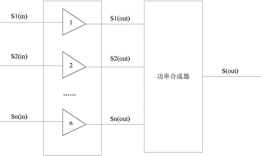
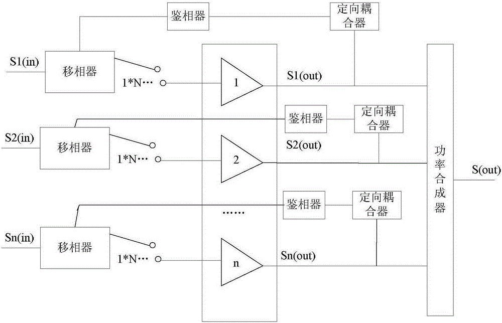
[0011] Such as figure 2 A phase alignment structure of a magnetic resonance radio frequency power amplifier shown, wherein the magnetic resonance radio frequency power amplifier includes a power amplification module of N power amplifier tubes, and a power combining module for inputting signals S1 (in), S2 of N paths (in), ... Sn(in) for power amplification and synthesis, the phase calibration structure includes: N switch matrix phase shifters with N output positions, N phase detectors and N directional couplers, N Among the input signals, each input signal is connected to a phase shifter and then connected to the input end of a power amplifier tube in the power amplifier module, and the output end of the power amplifier tube is connected to the input end of a directional coupler, and the directional coupler The output end of the phase detect...


PUM


Abstract

The invention relates to a phase calibration structure of a magnetic resonance radio frequency power amplifier. The magnetic resonance radio frequency power amplifier comprises power amplification modules of N power amplifier tubes and a power synthesis module, wherein the power synthesis module is used for power amplification and synthesis of N input signals. The phase calibration structure is characterized by comprising N phase shifters, N phase discriminators and N directional couplers; each input signal of N input signals is connected with one phase shifter and then connected with an input end of one power amplifier tube in one power amplification module, an output end of the power amplification tube is connected with an input end of one directional coupler, and an output end of the directional coupler is connected with one phase discriminator and then connected with a phase shifter input end corresponding to the signal; besides, output ends of all the power amplifier tubes are connected with the power synthesis module. The phase calibration structure has the advantages as follows: the phase difference generated by the power amplifier tubes is automatically compensated, phases of the output signals are consistent, and the optimum synthesis efficiency is realized.

Description

technical field [0001] The invention relates to a phase calibration structure of a magnetic resonance radio frequency power amplifier. Background technique [0002] The structure of the current magnetic resonance radio frequency power amplifier is shown in the appendix figure 1 As shown, the input signal is S1(in)=S2(in)=...=Sn(in), each input signal passes through a power amplifier tube, and the input signal is amplified to S1(out), S2(out), Sn (out). Theoretically, we hope that after the input signals of N channels pass through the power amplifier tube, the output signals obtained are also completely equal. Each input signal and output signal have two variables, one is the gain and the other is the phase; but in fact, due to various power The inconsistency of the amplifier tubes, especially the power of the nuclear magnetic resonance radio frequency power amplifier tubes is relatively large, and a single power amplifier tube can reach more than 1.5KW, so it is difficult ...

Claims


Application Information

Patent Timeline
Patent Type & Authority Applications(China)
IPC IPC(8): H03F1/07H03F3/189H03F3/20
Inventor 李应良
Owner XINGAOYI MEDICAL EQUIP CO LTD
Why Eureka
Try Eureka