Minimization maximum design method for alternating DFT modulation filter banks

A minimax and filter bank technology, applied in impedance networks, digital technology networks, electrical components, etc., which can solve the problems of difficult simultaneous control of frequency characteristics and reconstruction characteristics.

Active Publication Date: 2015-12-30
GUILIN UNIV OF ELECTRONIC TECH
View PDF4 Cites 6 Cited by
  • Summary
  • Abstract
  • Description
  • Claims
  • Application Information

AI Technical Summary

Problems solved by technology

[0004] What the present invention is to solve is the problem that the frequency characteristics and reconstruction characteristics of the existing over-sampled alternating DFT

Method used


Image

  • Minimization maximum design method for alternating DFT modulation filter banks
  • Minimization maximum design method for alternating DFT modulation filter banks
  • Minimization maximum design method for alternating DFT modulation filter banks

Examples


Embodiment Construction

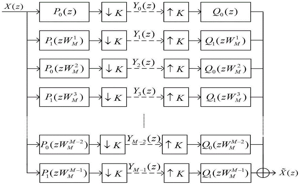
[0043] A minimum-maximum design method for alternating DFT modulated filter banks, comprising the steps of:

[0044] Step 1: The structure of the alternating DFT modulated filter bank is as figure 1 As shown, each subband filter of this alternating DFT modulated filter bank is expressed as a function of the prototype filter:

[0045] p 2 k ( n ) = p 0 ( n ) W M - 2 kn , ...


PUM


Abstract

The invention discloses a minimization maximum design method for alternating DFT modulation filter banks. The requirement for oversampling of reconstructed characteristics and frequency characteristics of the DFT modulation filter banks is converted into a function relative to prototype filter coefficients, then a design problem of alternating the DFT modulation filter tanks is converted into a constrained optimization problem, and finally minimization maximum algorithm is adopted for obtaining the optimal coefficient of the prototype filter. An aliasing component compensation mode is introduced into the design of oversampling of the DFT modulation filter banks for the first time for controlling aliasing errors, so that aliasing errors are effectively constrained, the reconstruction performance is improved, and the high-aliasing problem caused by stopband attenuation is avoided.

Description

technical field [0001] The invention belongs to the field of multi-rate signal processing, and in particular relates to a minimization-maximum design method of an alternating DFT (discrete Fourier transform) modulation filter bank. Background technique [0002] Multi-rate filter banks are widely used in speech signal processing, image processing, radar signal processing and so on. As a special kind of filter bank, DFT modulated filter bank has received special attention because of its simple design and low implementation cost. In recent years, some scholars have constructed a new class of DFT modulated filter banks, called alternating DFT modulated filter banks. In this type of filter bank, the adjacent sub-band filters are obtained by DFT modulation of different prototype filters, so the shapes of their amplitude responses are different, which is beneficial to the suppression of aliasing distortion. Due to the contradiction between aliasing distortion cancellation and hig...

Claims


Application Information

Patent Timeline
IPC IPC(8): H03H17/02
Inventor 蒋俊正周芳欧阳缮谢跃雷程小磊江庆郭云
Owner GUILIN UNIV OF ELECTRONIC TECH
Why Eureka
Try Eureka