Gas-liquid reactor and gas-liquid reactor group

A gas-liquid reactor and reactor technology, applied in chemical methods, chemical instruments and methods, and chemical/physical processes for reacting liquid and gas media, can solve problems affecting mass transfer and heat transfer, and achieve improved Utilization rate, enhanced heat and mass transfer effect, simple structure effect

Inactive Publication Date: 2016-01-06
南京通用化工设备技术研究院有限公司
View PDF8 Cites 1 Cited by
  • Summary
  • Abstract
  • Description
  • Claims
  • Application Information

AI Technical Summary

Problems solved by technology

None of these existing reactors can maximize the gas-liquid contact surface, which affects mass transfer and heat transfer

Method used


Image

  • Gas-liquid reactor and gas-liquid reactor group
  • Gas-liquid reactor and gas-liquid reactor group

Examples


Embodiment 1

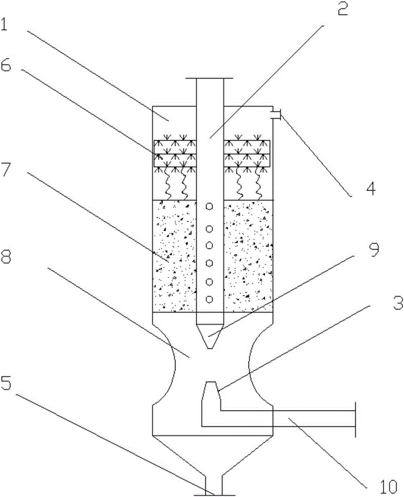
[0016] see figure 1 , a gas-liquid reactor, comprising a vertical tube reactor body 1, a liquid injection tube 2 and a gas injection tube 3, a gas outlet 4 is provided on the top of the vertical tube reactor body, a liquid outlet 5 is provided at the bottom, and the reactor body An annular catalyst layer 6 is fixedly arranged in the middle, and the reactor body also includes an annular steel wire mesh 7 arranged above the catalyst layer through a plurality of spring supports, and the liquid injection pipe 3 passes through the annular steel wire downward from the top of the reactor body 1 The net 7 and the catalytic layer 6 extend into the lower part of the reactor body, the gas injection pipe 3 passes through the side wall of the lower part of the reactor body and also extends into the lower part of the reactor body, and a section of the side wall of the lower part of the reactor body is recessed inwardly to form a throat 8, The outlet end of the liquid injection pipe and the ...

Embodiment 2

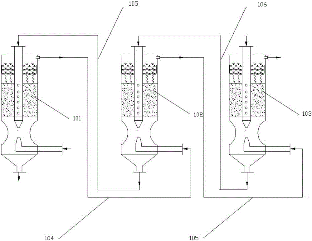
[0021] like figure 2 As shown, a gas-liquid reactor group is formed by connecting jet reactors described in 3 claims in series, which are respectively the first reactor 101, the second reactor 102, the third reactor 103, and the first reactor The gas outlet of 101 links to each other with the gas injection pipe inlet of the second reactor 102 through the first inlet pipe 104, and the gas outlet of the second reactor 102 links to each other with the gas injection pipe inlet of the third reactor 103 through the second inlet pipe 105; The liquid outlet of the third reactor 103 is connected with the liquid injection pipe inlet of the second reactor by the first liquid inlet pipe 106, and the liquid outlet of the second reactor 102 is connected with the liquid of the first reactor 101 by the second liquid inlet pipe 107. The injection pipe inlet is connected.

[0022] The gas material is continuously sprayed into the lower part of the first reactor 101 through the gas nozzle of t...


PUM


Abstract

The invention discloses a gas-liquid reactor. The gas-liquid reactor comprises a vertical tube type reactor body, a liquid injection tube and a gas injection tube, wherein a gas outlet is formed in the upper part of the vertical tube type reactor body, a liquid outlet is formed in the bottom, and a ring-shaped catalyst layer is fixed in the middle of the reactor body; a ring-shaped steel wire mesh supported above the catalyst layer through multiple springs is arranged in the reactor body; the liquid injection tube downwards penetrates through the ring-shaped steel wire mesh and the catalyst layer from the top end of the reactor body and extends into the lower part of the reactor body; the gas injection tube penetrates through the side wall of the lower part of the reactor body and extends into the lower part of the reactor body; a liquid nozzle opening downwards and a gas nozzle opening upwards are arranged at the outlet end of the liquid injection tube and the outlet end of the gas injection tube respectively and are arranged oppositely. The gas-liquid reactor has simple structure and large gas-liquid contact area, high-speed colliding mixing of the gas and the liquid of reactants can be realized, interphase mixing of the reaction materials is enhanced, and the heat and mass transfer effect is enhanced.

Description

technical field [0001] The invention relates to a gas-liquid reactor and a gas-liquid reactor group composed of a plurality of gas-liquid reactors connected in series. Background technique [0002] At present, there are many types of equipment for gas-liquid two-phase mixing, which can be divided into: (1) bubble column reactors in which gas is dispersed in the liquid phase in the form of bubbles, stirred bubble tank reactors according to the gas-liquid phase contact form and plate reactors; (2) spray, spray and Venturi reactors in which the liquid is dispersed in the gas phase in the form of droplets; (3) packed tower reactors and falling film reactors in which the liquid contacts the gas phase in a film-like motion . None of these existing reactors can maximize the gas-liquid contact surface, which affects mass transfer and heat transfer. Contents of the invention [0003] The invention provides a gas-liquid reactor, which has a simple structure and a gas-liquid contac...

Claims


Application Information

Patent Timeline
Patent Type & Authority Applications(China)
IPC IPC(8): B01J10/00
Inventor 宋佳佳李政辉王克刚李杰郝建祖
Owner 南京通用化工设备技术研究院有限公司
Why Eureka
Try Eureka