A tooling structure that can ensure the verticality of welding of reinforcement ribs, support columns and guide rails

A technology for supporting columns and reinforcing ribs, applied in welding equipment, auxiliary welding equipment, metal processing equipment, etc., can solve the problem that the center distance of two plane guide rails cannot be satisfied, the welding perpendicularity of supporting columns cannot be satisfied, and the production progress and product quality are affected. and other problems, to achieve the effect of simple structure, easy operation and improved production efficiency

Active Publication Date: 2016-10-12
SYMAX ELEVATOR CHINA
View PDF6 Cites 0 Cited by
  • Summary
  • Abstract
  • Description
  • Claims
  • Application Information

AI Technical Summary

Problems solved by technology

[0002] At present, the welding between the plane guide rails of the existing home elevator and the support columns and reinforcing ribs is made by the operator using four simple installation plates, placing the simple tooling plates on the welding platform, and then placing the plane guide rails and support columns to be welded. , The reinforcing ribs are placed on the simple tooling plate for welding, but this splicing method not only cannot meet the center distance between the two plane guide rails, but also cannot meet the welding verticality between the supporting column, the reinforcing rib and each plane guide rail. Seriously affected the production schedule and product quality, reducing production efficiency

Method used


Image

  • A tooling structure that can ensure the verticality of welding of reinforcement ribs, support columns and guide rails
  • A tooling structure that can ensure the verticality of welding of reinforcement ribs, support columns and guide rails
  • A tooling structure that can ensure the verticality of welding of reinforcement ribs, support columns and guide rails

Examples


Embodiment Construction

[0019] The specific implementation manner of the present invention will be described below in conjunction with the accompanying drawings.

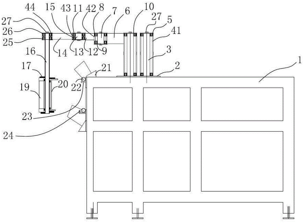
[0020] like figure 1 As shown, a tooling structure that can ensure the verticality of the welding of reinforcing ribs, support columns and guide rails includes a work frame 1, a base plate 2 is fixed on the work frame 1, and a plurality of first rotation axes are arranged on the surface of the base plate 2 along the vertical direction. 3. The first rotating shaft 3 is installed in the first rotating drum 41, one end of the first connecting rod 6 is connected to the first rotating drum 41, and the upper and lower surfaces of the other end of the first connecting rod 6 are respectively connected to the second rotating shaft fixing plate 8. The second rotating drum 42 is installed between two second rotating shaft fixing plates 8, and the second rotating shaft 7 is installed in the second rotating drum 42; one end of the second connecting rod...


PUM


Abstract

The invention relates to a tool structure capable of guaranteeing welding perpendicularity of reinforcing ribs, supporting columns and guide rails. The tool structure comprises a working frame, a first rotary shaft, a second rotary shaft, a third rotary shaft and a fourth rotary shaft, and further comprises a cantilever, wherein each rotary shaft is mounted in each rotary drum and capable of realizing rotary motion; the other end of the cantilever is provided with a pair of mounting plates; and one surface, opposite to the cantilever, of the working frame is further connected with a pair of tool plates. The tool structure is simple in structure and convenient in use; during welding operation, the supporting columns, the reinforcing ribs and the guide rails are opposite to an operator, so that the operation of the operator is convenient. The guide rails are arranged on each tool plate, and the tool plates are parallel to one another, so that a distance between the guide rails on the tool plates is fixed, and a central distance between the guide rails is guaranteed; the cantilever is perpendicular to the ground, and the mounting plates are additionally arranged on the cantilever, so that the reinforcing ribs and the supporting columns are also perpendicular to the ground, thereby guaranteeing the welding perpendicularity of the guide rails, the supporting columns and the reinforcing ribs and improving the production efficiency.

Description

technical field [0001] The invention relates to a guide rail processing equipment for a stair lift, in particular to a tooling structure capable of ensuring the perpendicularity of reinforcement ribs, support columns and guide rail welding. Background technique [0002] At present, the welding between the plane guide rails of the existing home elevator and the support columns and reinforcing ribs is made by the operator using four simple installation plates, placing the simple tooling plates on the welding platform, and then placing the plane guide rails and support columns to be welded. , The reinforcing ribs are placed on the simple tooling plate for welding, but this splicing method not only cannot meet the center distance between the two plane guide rails, but also cannot meet the welding verticality between the supporting column, the reinforcing rib and each plane guide rail. Seriously affected the production schedule and product quality, reducing production efficiency....

Claims


Application Information

Patent Timeline
Patent Type & Authority Patents(China)
IPC IPC(8): B23K37/04
CPCB23K37/0443
Inventor 陆庆江张晓燕
Owner SYMAX ELEVATOR CHINA
Why Eureka
Try Eureka