
Flexible circuit board and mobile terminal

A technology for flexible circuit boards and mobile terminals, which is applied in the direction of printed circuits, printed circuits, printed circuit components, etc. It can solve the problems of falling off, small contact area, and low pad adhesion strength, so as to enhance adhesion and ensure tight connection sexual effect

Active Publication Date: 2019-02-05
GUANGDONG OPPO MOBILE TELECOMM CORP LTD
View PDF4 Cites 0 Cited by
  • Summary
  • Abstract
  • Description
  • Claims
  • Application Information

AI Technical Summary

Problems solved by technology

However, since the pad is set on the flexible circuit board by means of solder, and the size of the pad is small, the contact area between the pad and the flexible circuit board is relatively small, and the amount of solder used is also small, resulting in the Low adhesion strength, easy to fall off from the flexible circuit board
When the flexible circuit board is welded to the main board or other components through the pad, due to the weak adsorption force of the pad on the flexible circuit board, it is easy to have a false soldering during welding
In addition, when the pads fall off from the flexible circuit board, it will also affect the connection between the flexible circuit board and the main board or other components, resulting in unsuccessful connection and affecting the normal operation of the whole machine

Method used


Image

  • Flexible circuit board and mobile terminal
  • Flexible circuit board and mobile terminal
  • Flexible circuit board and mobile terminal

Examples


Embodiment Construction

[0024] The following will clearly and completely describe the technical solutions in the embodiments of the present invention with reference to the accompanying drawings in the embodiments of the present invention. Obviously, the described embodiments are only some, not all, embodiments of the present invention. Based on the embodiments of the present invention, all other embodiments obtained by persons of ordinary skill in the art without making creative efforts belong to the protection scope of the present invention.

[0025] For the convenience of description, spatial relative terms such as "under", "below", "below", "over", "upper" and other spatial relative terms can be used to describe the One element or feature shown in relationship to another element or feature(s). It will be understood that when an element or layer is referred to as being "on," "connected to," or "coupled to" another element or layer, it can be directly on, directly on, or directly on the other elemen...


PUM


Abstract

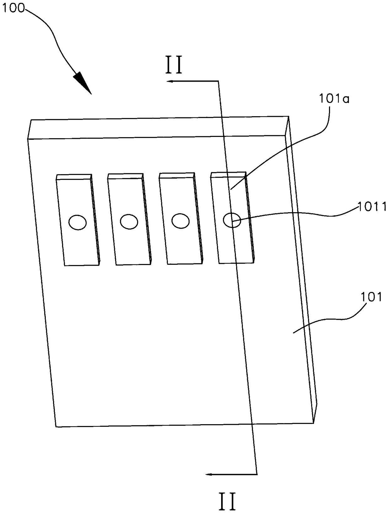
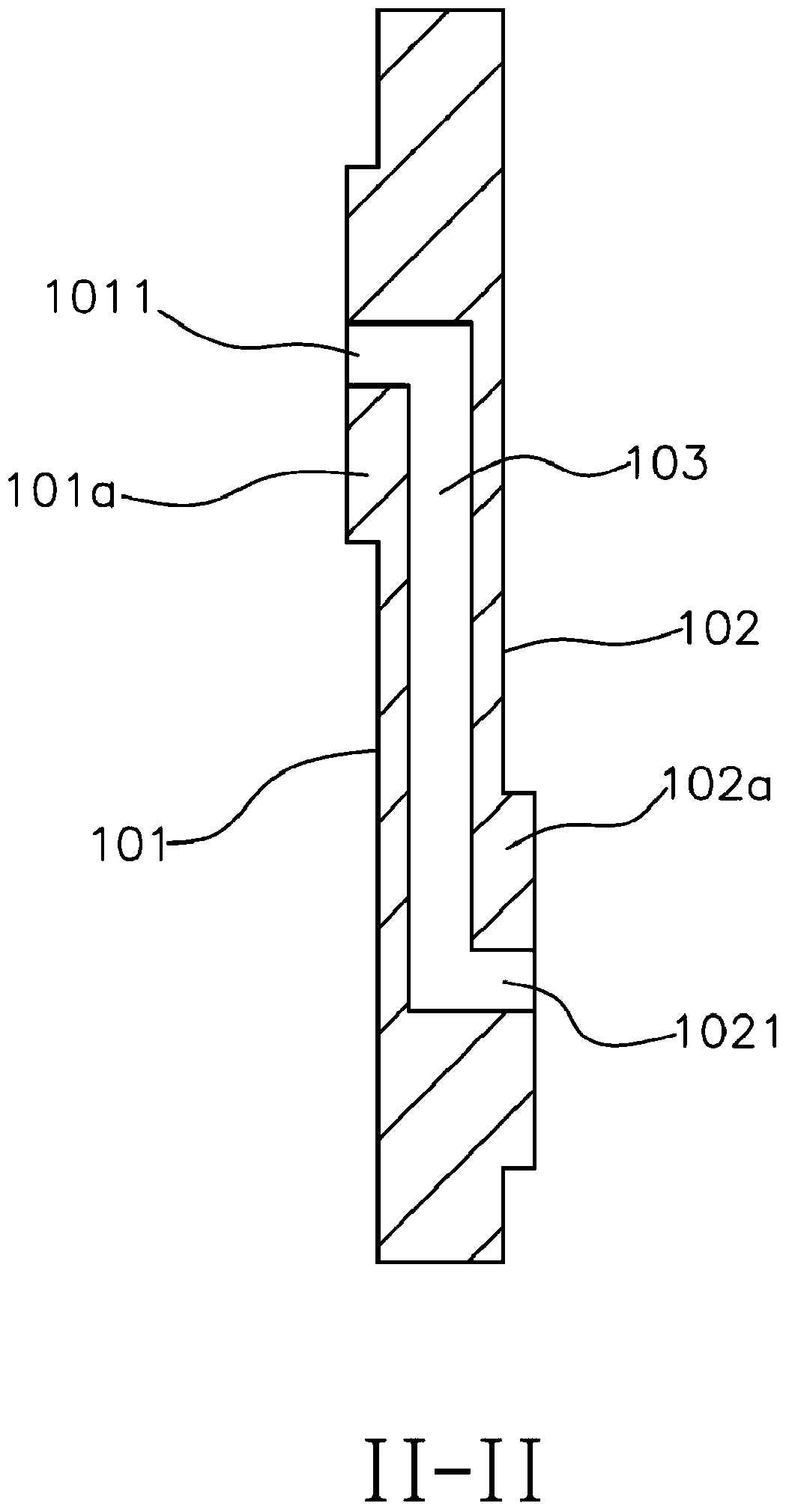
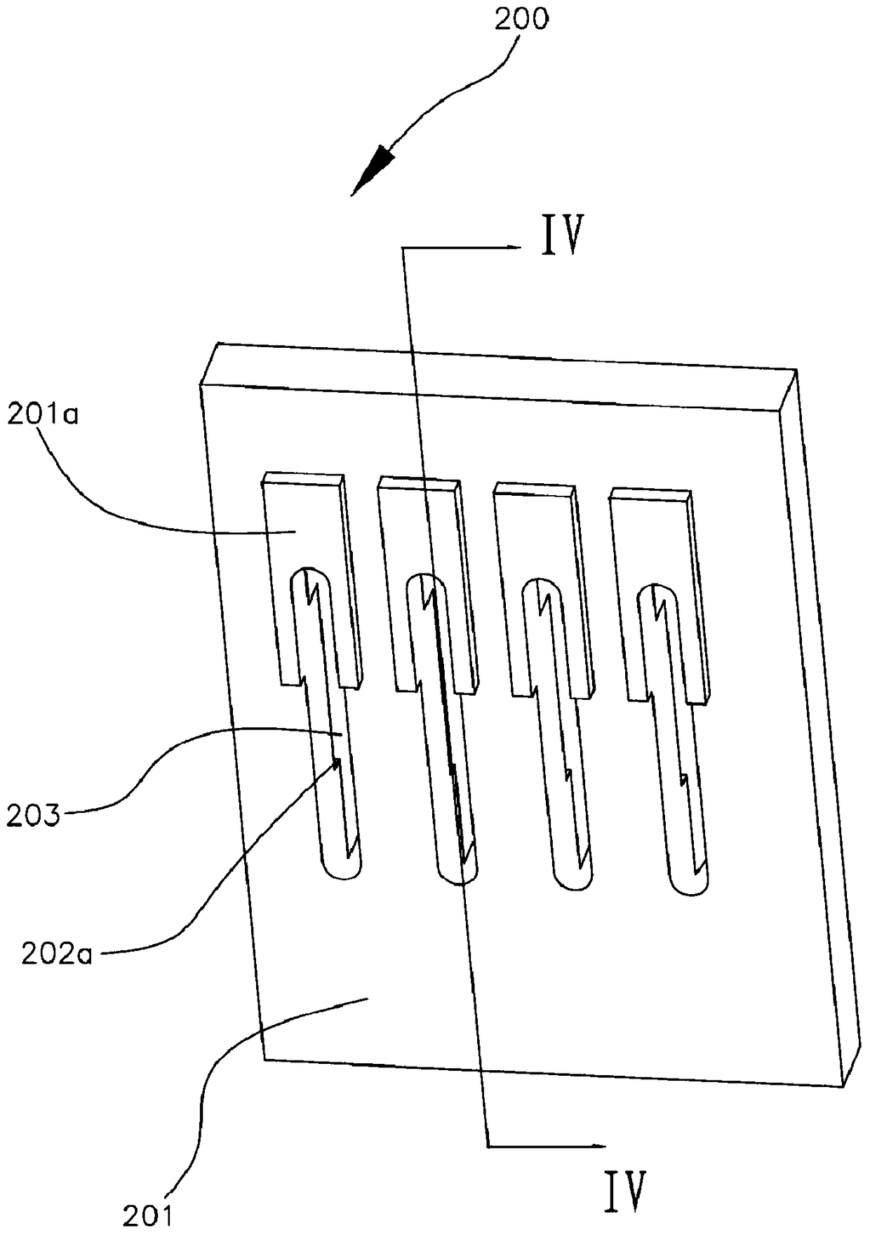
The invention provides a flexible printed circuit board, comprising a first side and a second side which are arranged face to face, wherein the first side is provided with at least one first bonding pad; the second side is provided with at least one second bonding pad corresponding to the at least one first bonding pad; a tin guiding channel is formed between each first bonding pad and the corresponding second bonding pad, the tin guiding channel is formed in the flexible printed circuit board and communicates the first bonding pad and the corresponding second bonding pad, and the center distance between the first bonding pad and the corresponding second bonding pad which are communicated by the tin guiding channel is a preset numerical value. According to the flexible printed circuit board provided by the invention, the tin guiding channel is used for connecting each first bonding pad and the corresponding second bonding pad together; by virtue of the circulating function of the tin guiding channel, soldering tin can flow from the first bonding pad to the surface of the second bonding pad and therefore a lot of soldering tin can be attached to the surfaces of the first bonding pad and the second bonding pad and further the first bonding pad or the second bonding pad can be prevented from falling off from the flexible printed circuit board. In addition, the invention further provides a mobile terminal comprising the flexible printed circuit board.

Description

technical field [0001] The invention relates to the field of circuit boards, in particular to a flexible circuit board and a mobile terminal. Background technique [0002] Flexible Printed Circuit (FPC) is a printed circuit board made of flexible materials. It has the advantages of high wiring density, light weight, thin thickness and soft material. It can be bent, wound and folded. , Therefore, it is widely used in the conductive system of various modern electronic products. [0003] At present, in order to realize the connection and fixation between the flexible circuit board and the main board or other components, soldering pads are usually provided on the flexible circuit board to solder and fix the main board or other components to the flexible circuit board. However, since the pad is set on the flexible circuit board by means of solder, and the size of the pad is small, the contact area between the pad and the flexible circuit board is relatively small, and the amount...

Claims


Application Information

Patent Timeline
Patent Type & Authority Patents(China)
IPC IPC(8): H05K1/11
CPCH05K1/113H05K1/118H05K2201/09481
Inventor 曾元清
Owner GUANGDONG OPPO MOBILE TELECOMM CORP LTD
Learn More