Lathe clamp and lathe

A lathe jig and jig technology, applied in the direction of clamping, clamping device, manufacturing tool, etc., can solve the problems of inconvenient clamping, insufficient clamping, easy to loose, etc., and achieve convenient clamping, convenient processing and manufacturing, and processing. high-quality effects

Active Publication Date: 2016-01-06
CHONGQING RUIJIA MACHINERY CO LTD
View PDF5 Cites 2 Cited by
  • Summary
  • Abstract
  • Description
  • Claims
  • Application Information

AI Technical Summary

Problems solved by technology

[0003] The object of the present invention is to provide a lathe clamp to improve the inconvenience of mounting and clamping the existing lathe processing bars and the situation that the clamping is not firm enough and easy to loosen

Method used


Image

  • Lathe clamp and lathe
  • Lathe clamp and lathe
  • Lathe clamp and lathe

Examples


Embodiment Construction

[0034] In the machining production process, fixtures are often used for processing operations. Sometimes the materials to be processed are not regular, so different fixtures are required to adapt to the operation, especially for bar-type workpieces. Due to the irregularity of the workpiece, It is inconvenient to use the traditional fixture for clamping, and after a long processing time, there will be looseness between the workpiece and the fixture, it is difficult to ensure the firmness, and it is not easy to process

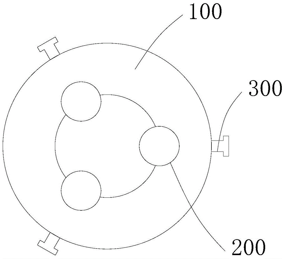
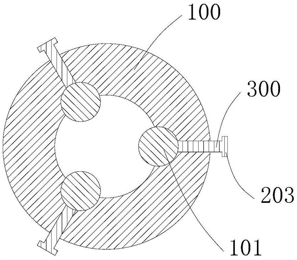
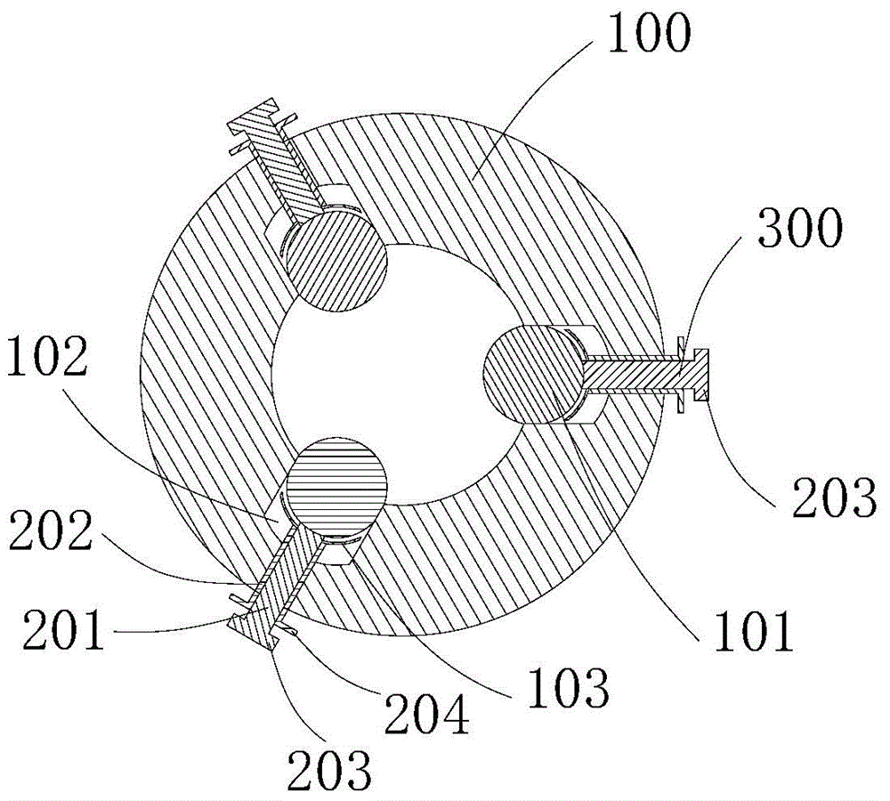
[0035] In view of this, the designer of the present invention has designed a lathe clamp and a lathe, the lathe clamp includes a clamp body and a clamp housing, the clamp body is installed on the clamp housing, and the clamp body includes a cylindrical The chuck, the cylindrical chuck is controlled by bolts, that is, when the workpiece is placed in the space surrounded by a plurality of cylindrical chucks, by screwing the bolts, the plurality of cylindrical chuck...


PUM


Abstract

The invention provides a lathe clamp and a lathe, and belongs to the field of mechanical processing equipment. The lathe clamp comprises a clamp housing and a clamp main body, wherein the clamp main body comprises a plurality of cylindrical chucks which are uniformly arranged in a peripheral direction of the clamp housing; central lines of the cylindrical chucks extend in an axial direction of the clamp housing; a plurality of threaded holes are respectively formed in positions, corresponding to the cylindrical chucks, on the clamp housing; the threaded holes are arranged at intervals in an axial direction of the clamp housing; bolts are in corresponding threaded connection in the threaded holes; the clamp main body is provided with a connecting part and a clamping part which are coaxially arranged, and the connecting part is inserted into the clamp housing; the connecting part is movably connected with a mounting part; the clamp housing and the clamping part are connected though a bolt, and the clamp housing and the connecting part are connected though a bolt; and the bolts are screwed up, so that the cylindrical chucks move in the radial direction of the clamp housing. The lathe comprises the lathe clamp. The clamp is convenient and quick in operation and good in clamping effect; and the lathe is high in processing precision, and safe and reliable to process.

Description

technical field [0001] The invention relates to the field of machining equipment, in particular, to a lathe fixture and a lathe. Background technique [0002] In the machining production process, fixtures are often used for processing operations. Sometimes the materials to be processed are not regular, so different fixtures are required to adapt to the operation, especially for bar-type workpieces. Due to the irregularity of the workpiece, It is inconvenient to use the traditional fixture for clamping, and after a long processing time, there will be looseness between the workpiece and the fixture, it is difficult to ensure the firmness, and it is not easy to process. Contents of the invention [0003] The object of the present invention is to provide a lathe clamp to improve the inconvenience of mounting and clamping the existing lathe processing bars and the situation that the clamping is not firm enough and easy to loosen. [0004] The purpose of the present invention i...

Claims


Application Information

Patent Timeline
IPC IPC(8): B23Q3/12
CPCB23Q3/12B23Q2703/10
Inventor 刘自力
Owner CHONGQING RUIJIA MACHINERY CO LTD
Why Eureka
Try Eureka