Built-in integrated water joint direction changing mechanism for single power, synchronous two-way mixing pile driver

A technology of changing direction mechanism and two-way stirring, applied in sheet pile wall, foundation structure engineering, construction, etc., can solve the problems of high manufacturing cost, large size, inconvenient installation, etc., and achieve the expansion of connotation and extension, low manufacturing cost, The effect of expanding the range

Active Publication Date: 2018-01-02
天津至简工程技术研究院有限公司
View PDF8 Cites 0 Cited by
  • Summary
  • Abstract
  • Description
  • Claims
  • Application Information

AI Technical Summary

Problems solved by technology

[0002] In the construction of mixing piles in railway, highway, construction, municipal, water conservancy, and port projects, the pile forming method of the mixing pile machine usually adopts the single-direction rotating drilling and stirring of the drill bit, and the construction method of pile formation is very prone to occurrence of slurry and clogging during construction. Drilling phenomenon, and low efficiency, quality is not easy to guarantee
There are literatures that use dual motors and double drill pipes for bidirectional drilling and mixing, although the drilling efficiency and pile quality are improved, but the pile driver needs to be modified or remanufactured, the installation is complicated, and the cost of pile driver modification and equipment usage is high
[0003] like figure 1 As shown, the water joint 12 of the existing CN200810052384.6 patent technology is usually installed on the upper or lower part of the steering mechanism 13, the structure is complex, the manufacturing cost is high; the size is large, and the installation is inconvenient. figure 1 Please refer to the embodiment of the present invention part for other symbols in , and the same components have the same symbols

Method used


Image

  • Built-in integrated water joint direction changing mechanism for single power, synchronous two-way mixing pile driver
  • Built-in integrated water joint direction changing mechanism for single power, synchronous two-way mixing pile driver
  • Built-in integrated water joint direction changing mechanism for single power, synchronous two-way mixing pile driver

Examples


Embodiment Construction

[0016] Below in conjunction with accompanying drawing and specific embodiment the present invention is described in further detail:

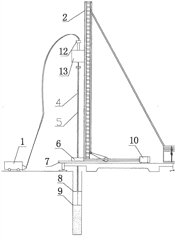
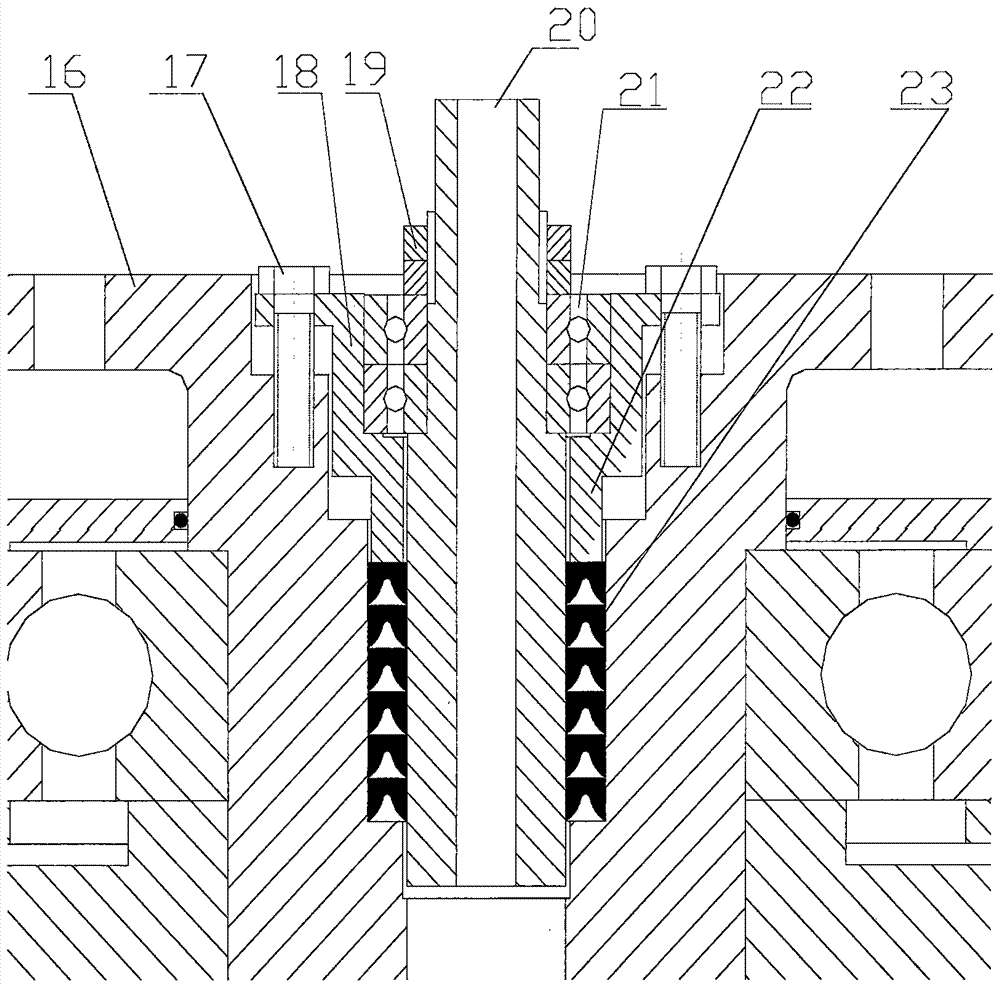
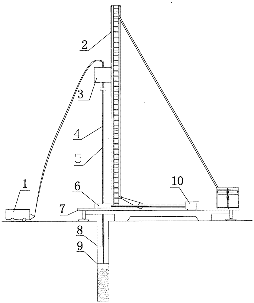
[0017] Such as figure 2 As shown, the built-in integrated water joint direction-changing mechanism for single-power, synchronous two-way mixing pile driver of the present invention includes a direction-changing mechanism and a water joint. in the transmission shaft 16.

[0018] Specifically, the top inner chamber of the transmission shaft 16 of the change-of-direction mechanism is provided with an expansion chamber, and the bottom end of the delivery shaft 20 of the water joint is inserted below the bottom of the transmission shaft 16 expansion cavity, and the delivery shaft 20 in the expansion cavity A pair of bearings 21 are set on the outer wall of the upper part. The bearing housing 18 located outside the bearings 21 is fixed in the expansion cavity. The delivery shaft 20 is fixed on the inner ring of the bearing 21 through a nut 19. It is...


PUM


Abstract

The invention discloses a built-in integrated water joint direction changing mechanism for a single-power, synchronous two-way stirring pile machine. in the transmission shaft. The top inner cavity of the transmission shaft of the direction changing mechanism is provided with an expansion cavity, the bottom end of the delivery shaft of the water joint is inserted below the bottom of the transmission shaft expansion cavity, and a pair of bearings are set on the upper outer wall of the transmission shaft in the expansion cavity. The bearing seat on the outer side of the bearing is fixed in the expansion cavity, and the conveying shaft is fixed on the inner ring of the bearing through a nut. At the bottom of the expansion cavity, there is a packing that acts as a seal on the outside of the conveying shaft. orchid. The built-in integrated water joint direction change mechanism of the present invention has both the direction change function and the slurry delivery function, small size, light weight, novel and simple mechanism, low manufacturing cost, and convenient installation; the inner through hole is large, and can transport cement slurry and cement. Various curing materials for mortar, cement slurry, and concrete expand the range of curing materials for mixing piles.

Description

technical field [0001] The invention relates to a stirring pile driver, in particular to a built-in integrated water joint direction-changing mechanism for a single-power, synchronous two-way stirring pile driver. Background technique [0002] In the construction of mixing piles in railway, highway, construction, municipal, water conservancy, and port projects, the pile forming method of the mixing pile machine usually adopts the single-direction rotating drilling and stirring of the drill bit, and the construction method of pile formation is very prone to occurrence of slurry and clogging during construction. drill phenomenon, and the efficiency is low, and the quality is not easy to guarantee. There are literatures that use double motors and double drill pipes for bidirectional drilling and mixing, although the drilling efficiency and pile quality are improved, but the pile driver needs to be modified or remanufactured, the installation is complicated, and the cost of pile...

Claims


Application Information

Patent Timeline
Patent Type & Authority Patents(China)
IPC IPC(8): E02D5/46E02D15/04
Inventor 徐玉杰徐常晟任洪玺王晓李孟雷宋帅王景瑞陈永良吕连月周敬叶刘晓红王云飞于玉彪任作伟
Owner 天津至简工程技术研究院有限公司
Why Eureka
Try Eureka